Maker Pro
Maker Pro

LED Strips blink on all X10 circuits

Our house has an extensive X10 light switch system, about 45 fluorescent fixtures, and 8 exterior lights.
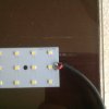
I have started or replace the fluorescent ballast and lamps with 48" LED strips and drivers.

When a switch is turned on several, but not all led strips on the circuit will blink, on and off at a steady rate. The on/off rate is steady, but the fixtures may or may not be in rhythm with one another.

The X10 system was installed in 2000, over time I have had some random lights turning on for some unknown reason.

There are some dimmer switches in the system, but I have not changed any of the fixtures on dimmer circuits yet.

Does anyone know how to diagnose why the LED will not work with X10?
 
Hi Blayson,
The X10 modules you have are probably pre-CFL modules. These did cause problems with driving leds.
You might want to upgrade to CFL compatible modules. Not 100% sure though.
Are your light modules ceiling mounted?
Or adaptor and wireless switch?.

Martin
 
The fixtures are 2x4, four lamp troffers. The switches are the x10 component. All the x10 switches are in wall mounted as normal switches. There is one additional controller which is also mounted in wall, that controls three circuits and has an all on/all off switch.

Most of these switches are 15 yrs old. Since my first post I have converted two fixtures in my closet upstairs which has a newer Leviton Decora switch. It operated fine at first. Then I noticed that if I left this closet light on and used the all off to make sure all the downstairs lights were off, this closet light began blinking like the others. It is on a different house code and was still affected. It took several on off cycles at its switch to stop the blinking.
 
Something very strange is going on there.
What led strips and drivers are you using? (voltage and amperage). What switches?
It still could be that their isn't sufficient load on the switches. What part numbers are they?
Have they got the led in the centre and touch operated?
I can see if I can duplicate your problem using my X10 system.

Martin
 
the strips are approx 42" long, with two rows of LED's. each to replace two 40 watt tubes. Not touch operated. The process is remove the ballast and tombstone connectors and screw the strips to the troffer box and install the driver, about half the size of ballast. white to white, black to black, for power side. red and blue for strip side.
I will get details, in the morning and answer back.. Grandson football this evening
 
Here is what I have

I have attached some photos of the installation in one area.
The driver details:
Model JSY-EMC40W(10S4P)
Input: Ac120-260v 50-60Hz
Output: DC26-36v. 1200mA -+6%
TC:70c. TA:40c. PF:>/0.9

LED Strips have no details, (from China)

image.jpeg

image.jpeg
 
Last edited by a moderator:
Hi Blayson,
I can see three rows of leds not two.
Is it possible to get a picture of the back of the led board to see how they are connected? And also how many leds there are in total on both boards.
The led drivers might not be sufficient at 1.2A.

Martin
 
Sorry for delay, there are 70x3, 210 LEDs per strip. The driver is supposed to be rated for two strips.
The back is slick, no connections, apparently they are sandwiched.

Thank you for your help and interest
 

Attachments

  • image.jpeg
    image.jpeg
    275.8 KB · Views: 113
  • image.jpeg
    image.jpeg
    283 KB · Views: 99
Seems a lot of work when a direct replacement tube is available for the existing 40w tubes.
Kit comes with a replacement "starter fuse" to fit to the existing starter base.
Note that they are mostly not suited to many existing dimmers etc. as with many LED fittings and drivers.
 

Attachments

  • fluroLed.jpg
    fluroLed.jpg
    6.8 KB · Views: 83
It has turned in to a lot of work.. When we changed them out at office, it went smooth. More light, less energy, we hope.

I just used my meter to check voltages.
120v - 122v to all the drivers.
16-17v dc out of the ones blinking
19v dc out of the two not blinking
 
Can you put your meter in series with the led strips to check the current?
Then you would have to double it because you are running two strips.
Depending on how those leds are connected series/parallel, gives a huge difference in current.
If I remember correctly, I got a difference of between 550ma and 1250ma per strip.
Your supply is only 1200ma.

EDIT: That was using 36 volts, 3.2Vf and 25ma.

Martin
 
How do I put meter 'in series', I am handy with tools, but no real electrical knowledge.

The strips and drivers are from China so there may be big variable in output.. In trying to meet a price point I wonder if the supplier supplied drivers that marginally meet requirements or maybe some strips need more power. The strips don't have a minimum power stamped unless it is in the series of numbers above.
Those numbers are the only information anywhere on them.
 
To check the current, take out the single wire from the driver to the connector. connect the meter between the single wire and the two wires in the connector. the red wires.
You will probably need to change the meter probe into the A terminal. Unless it's autoranging.
Check your meter online if you can't find the manual..


upload_2015-10-27_14-6-31.jpeg

Martin
 
Top