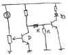
Design a circuit that will turn on a small incandescent lamp when darkness falls.
It should use a light-dependent resistor (LDR), a potentiometer to set the trigger level, and one or more darlington transistors, and other components as required.
Component values are not required.
(Correct answer attached).
There are a couple of things I am not sure of:
*I am not too sure how the current would flow (from the beginning to the end) and if it would split at the common points e.g. at the beginning, if one current would flow directly to earth, the other would flow through the base of the darlington, simultaneously.
*Shouldnt R be connected to the positive rail (parallel to the LED), so that it is in line with the other R (by voltage division)?
*How would you know that you must draw a darlington transistor connected as an earthed emitter, as opposed to emitter-follower?
*What does using 2 darlingtons give you in this specific circuit, besides amplifying the current?
")