I have also got LC circuit task.
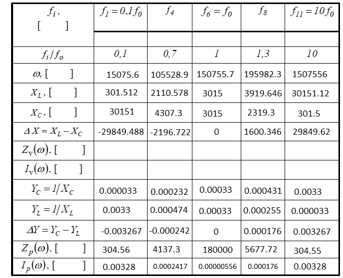
I add table, where are values, which I have to calculate (I guess all denotations/symbols are international):
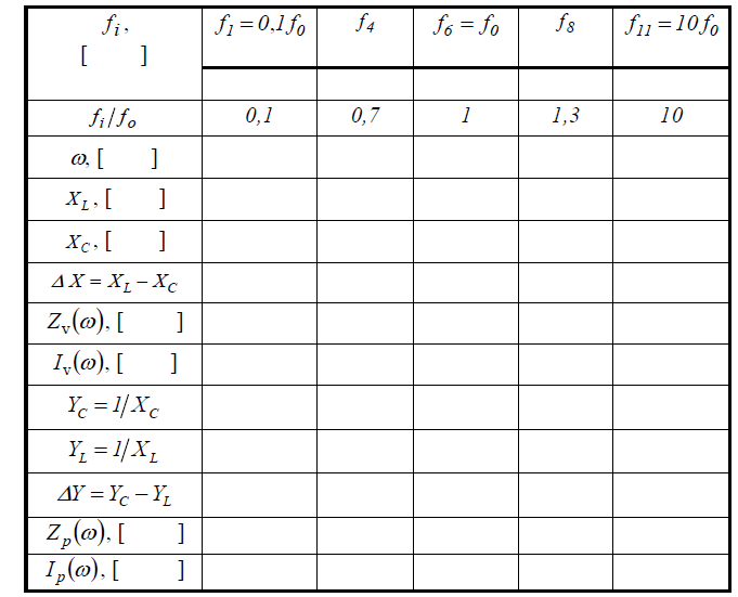
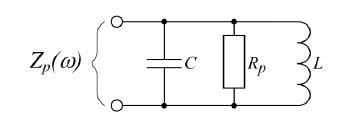
1.1 We have got parallel LC circuit.
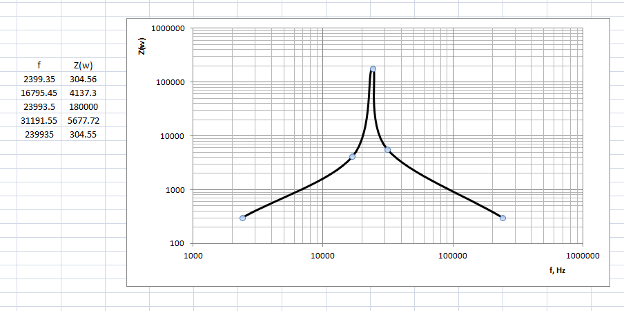
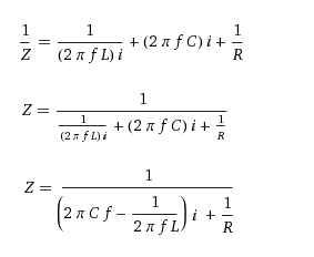
Have to calculate frequency f0, ratio of charge Q and total impedance Z(w) in the range (0.1 .. 10)f0.
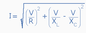
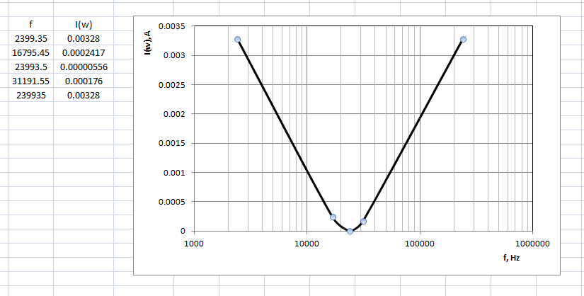
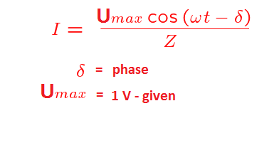
And have to calculate input current (effective value) using given frequencies in the table, if we know that is added sinusoidal voltage amplitude 1 V to the circuit.
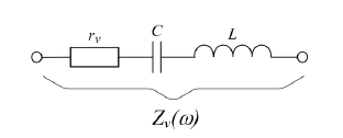
1.2 We have got series LC circuit.
GIVEN:
Rp = 180 kOhms = 180 * 10^3 Ohms
C = 2200 pF = 2200 * 10^(-12) F
L = 20 mH = 20 * 10^(-3) H
What I have already done:
I calculated frequency f0 for parallel and series circuits: w0 = 2*pi*f0 = 1/sqrt(L*C)
w0 = 1/sqrt(20*10^(-3) * 2200*10^(-12)) = 500000/sqrt(11) = ~150755.7
f0 = w0/(2pi) = (500000/sqrt(11))/2pi = 250000/(sqrt(11)*pi) = ~23993.5 Hz
XL = XC
XL = w * L = (500000/sqrt(11)) * 20*10^(-3) = 10000/sqrt(11) = ~3015
XC = 1/(w*C) = 1/((500000/sqrt(11))*2200*10^(-12)) = 10000/sqrt(11) = ~3015
for parallel circuit: Q = Rp/(w0*L) = 180*10^3/((500000/sqrt(11))*20*10^(-3)) = 18 sqrt(11) = ~60
Yc = 1/Xc = 1/(10000/sqrt(11)) = sqrt(11)/10000 = ~ 0.00033
YL = 1/XL = 1/(10000/sqrt(11)) = sqrt(11)/10000 = ~ 0.00033
I have got lack of understanding, why I have to calculate delta Y and delta X? Or I have done something wrong? XL = XC and YC = YL.. where is the point?
And speaking about parallel circuit, how to do this task - calculate input current (effective value) using given frequencies in the table, if we know that is added sinusoidal voltage amplitude 1 V to the circuit?
Later I will start to solve other tasks with series circuit, but yes, can someone can explain my questions..
I add table, where are values, which I have to calculate (I guess all denotations/symbols are international):
1.1 We have got parallel LC circuit.
Have to calculate frequency f0, ratio of charge Q and total impedance Z(w) in the range (0.1 .. 10)f0.
And have to calculate input current (effective value) using given frequencies in the table, if we know that is added sinusoidal voltage amplitude 1 V to the circuit.
1.2 We have got series LC circuit.
GIVEN:
Rp = 180 kOhms = 180 * 10^3 Ohms
C = 2200 pF = 2200 * 10^(-12) F
L = 20 mH = 20 * 10^(-3) H
What I have already done:
I calculated frequency f0 for parallel and series circuits: w0 = 2*pi*f0 = 1/sqrt(L*C)
w0 = 1/sqrt(20*10^(-3) * 2200*10^(-12)) = 500000/sqrt(11) = ~150755.7
f0 = w0/(2pi) = (500000/sqrt(11))/2pi = 250000/(sqrt(11)*pi) = ~23993.5 Hz
XL = XC
XL = w * L = (500000/sqrt(11)) * 20*10^(-3) = 10000/sqrt(11) = ~3015
XC = 1/(w*C) = 1/((500000/sqrt(11))*2200*10^(-12)) = 10000/sqrt(11) = ~3015
for parallel circuit: Q = Rp/(w0*L) = 180*10^3/((500000/sqrt(11))*20*10^(-3)) = 18 sqrt(11) = ~60
Yc = 1/Xc = 1/(10000/sqrt(11)) = sqrt(11)/10000 = ~ 0.00033
YL = 1/XL = 1/(10000/sqrt(11)) = sqrt(11)/10000 = ~ 0.00033
I have got lack of understanding, why I have to calculate delta Y and delta X? Or I have done something wrong? XL = XC and YC = YL.. where is the point?
And speaking about parallel circuit, how to do this task - calculate input current (effective value) using given frequencies in the table, if we know that is added sinusoidal voltage amplitude 1 V to the circuit?
Later I will start to solve other tasks with series circuit, but yes, can someone can explain my questions..
")