Maker Pro
Maker Pro

JVC AX-R551X PROBLEM

Hello ! i am back with some more trouble :)

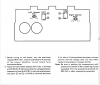
I have a JVC AX-R551X on my bench. When it came to me all the power transistors where burned (2sa1264 and s2c1381) as well as a number of other transistors and diodes.

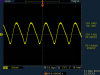
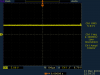
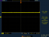
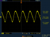
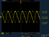
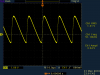
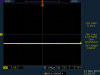
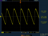
I replaced them all with new and now the amplifier will power on, all controls in front panel work but volume at the speakers is very very low even at high volume setting.

I have read that at an other JVC model the same problem was caused by a bad diode at the muting circuit. in this amp i am not sure where to look.

Here is a list of what i have found bad and replaced.

Strange was that after noticing that r801 was externally burned i removed it checked it and gave me a different value than the 333k stated in the service manual (I replaced it with a 33k). Could it be because it was damaged ?

TRANSISTORS
Q771, Q722 = 2SA1264
Q769, Q770 = 2SC3181
Q755, Q756, Q759, Q760 = 2SA933
Q763, Q764 = 2SA1038
Q765, Q766 = 2SC2235
Q767, Q768 = 2SA965

RESISTORS
R790, R792 = 10Ω 1/4W
R831 = 22Ω 1W
R801 33K 1/4W

I have the service manual in pdf but can not upload here because it is 9MB
i got it from here :
http://elektrotanya.com/jvc_ax-r551bk.pdf/download.html

Any help appreciated THANK YOU.
 
Last edited:
Also when i activate both A and B output speakers then there is no sound at all but each of them separate will give output at both left and right channels.
 
.


Sir HellasTechn. . . . . . .

WHAT . . .No one wants to help you . . . . .?
After you spending all of that money for those semiconductors .

Is my schematic different from yours . . . .as those bleeder resistors across the main power supply are 33k vice 330k .

Will the amp drive headphones OK ?
Do a metering for DC voltage, using ground reference, and positive probe over at pin 2 of the dedicated protection IC # 901 / TA7317P.
If there is significant DC voltage on the speaker line of either power output section, that input voltage will pop the RY901 to disconnect the speakers.
If any question, just do a quick shorting of pin 2 to ground to see if you hear the reay click and you get sound.

The other protect feature is the Q901 Q902 Q903 sampling transistors being associated with current levels of the power output stages.
A fault there will cause the same relay cutout, by their triggering pin 1 of that IC.

The only diode I see being in that circuitry is D903 over shunting the RY 901 . . . .I don't expect it . . . but lift one lead and test .

Standing by . . . . .


73's de Edd


.
 
Will the amp drive headphones OK ?
I have not tested that.

The relay clicks once after the amp is powered up and then it stays like that.
Is my schematic different from yours . . . .as those bleeder resistors across the main power supply are 33k vice 330k .

You are correct. The diagram says 33K. I have to check what resistor i have put in. I think i just typed the value wrong but i dont remember for sure.

If there is significant DC voltage on the speaker line of either power output section, that input voltage will pop the RY901 to disconnect the speakers.

If there is significant DC voltage on the speaker line of either power output section, that input voltage will pop the RY901 to disconnect the speakers.

If that was the case then i think that i would not be able to hear any sound from the speakers at all.
right now i can hear sound, i can control the volume but the sound volume is really low.

OK some more info. when i turn the input audio volume of my mp3 too high i can hear the amp playing a little louder but distorted. That makes me think that either the preamplifier circuits are not working or the power amplifier stage is not working (probably the poweramp). The output transistors are not even getting warm while three TO-220 on the other side of the board mounted on heatsinks get really hot (i have measured them and are not bad). I will get back to you to let you know exactly which ones.

I will do the test you suggested though !

Thank you so much for your help !
 
P.S.

On the front panel PCB i have located the cpu and dissconected the mute pin (pin 23 or 24) by cutting it's jumper wire. That did not make any difference.

Also i can not make this adjustment

R787 voltage betwee A and B is always 0 no matter the position of R751

and

R788 voltage betwee C and D is always 2.5mv no matter the position of R752

I sould also mention that Left channel volume on the speaker is a little lower than Right channel
 

Attachments

  • amp.png
    amp.png
    55.5 KB · Views: 231
Last edited:
I checked again the old resistors 801 and 831 and although smoked and discoloured they are good. 801=33K 831=22Ω

And yes the new 801 i have put is 33K not 330K.
 
Ok I have news.
Without a reason now when i power up the amplifier. The diaplay flashes for a second ans stays off and after the speakers relay clicks on i get a buzzing sound from the speakers...
 
.


All Hail . . .the Great and Mighty . . . . .Constantine

R788 voltage betwee(sic) C and D is always 2.5mv no matter the position of R752

That's telling us that there is no great voltage disparity between the same value emitter resistors of the NPN and PNP power output transistors on both channels.
Also there is being no HIGH current pull in either output stage.

On the front panel PCB i have located the cpu and dissconected the mute pin (pin 23 or 24) by cutting it's jumper wire. That did not make any difference.

Put that back as it was originally and we will work with the mute aspect, if it becomes more apparent as being an involved factor . . .later on.


OK some more info. when i turn the input audio volume of my mp3 too high i can hear the amp playing a little louder but distorted.

Logical . . . . on both the proportional increase in volume and then the onset of distortion, with you then exceeding this amps 200MV input threshold specification.

Strange was that after noticing that r801 was externally burned

With that constant DC level across that R801 bleeder, one would not expect but a moderate warming with the voltage constantly being across it. BUT, as you can see, its contra-polar companion C802 is NOT experiencing that same heating effect . . .right ?.

Factoid:
If you have a raw DC power supply feeding into either a discrete designed regulator pass transistor, a power amp transistor or a 3 terminal regulator, if it is not adequately filtered and thereby not being properly bypassed in that supply ; those secondary components will heat up.

Present conditions:
The Q801 and Q802 xstrs . . . . . are used as +15Vdc and +5Vdc regulators and both tap off from that +63 Vdc supply, that is relying upon MASSIVE C801 for its filtering.
(Actually Q806 is also a +5 Vdc regulator but it only has the paltry power demand of driving the volume control motor.)
Currently you say that Q801 and Q802 are WARM.
The next logical test is to pull out ye olde "silly scope" and check for ripple content across C801 and then C802.
I am expecting C801 to be showing RIPPLE city on the screen . . . .as compared to the minimal ripple being found across C802.
The nominal DC level at C801 PLUS the added ripple sitting on top of that DC level could account for that extra warming of bleeder R801.

Meaning that filter C801 has declined capacitance, effective filtering wise.
Also relating to the audio hum presence..

Check it out.

No illustrations were involved in this posting .


73's de Edd


.
 
Last edited:
Ok I have news.
Without a reason now when i power up the amplifier. The diaplay flashes for a second ans stays off and after the speakers relay clicks on i get a buzzing sound from the speakers...

This problem went away after i removed the boars, desoldered C801 and C802 measured them and put all back together. There is no noise in the speakers any more.

The problem that cause that was me having forgotten to mount the grounding screws of the heatsink and pcb.

By the way capacitors gave me value 1032mf (not uf) ESR 0.8Ω and V loss 0.9%
1010mf ESR 0,7Ω and V loss 0.6%
 
Last edited:
Now i have the pcb removed but still wired up and i can take measurements.
I will get back to you with Oscope images of the capacitors and transistors and IC901 (TA7317P) pin 2 referenced to ground.
 
Now i have some interesting images to show you. All measurements where referenced to ground with only exception C801 and C802!

For all measurements the amplifier was powered on, No signal to inputs, input selector set to CD and volume knob turned to 50%

First comes Q801 measurement taken with reference to ground (heatsink)
 

Attachments

  • Q801 base.PNG
    Q801 base.PNG
    7.9 KB · Views: 126
  • Q801 collector.PNG
    Q801 collector.PNG
    7.8 KB · Views: 158
  • Q801 emmiter.PNG
    Q801 emmiter.PNG
    7.6 KB · Views: 133
Last edited:
Capacitors C801 and C802 measured with Oscope probe between capacitor legs also probe set to X10
 

Attachments

  • C801.PNG
    C801.PNG
    7.8 KB · Views: 157
  • C802.PNG
    C802.PNG
    7.8 KB · Views: 144
And now power transistors referenced to ground !

In all of them Collectors where measured with probe set to X10 because voltage was out of scale.
 

Attachments

  • Q769 BASE.PNG
    Q769 BASE.PNG
    13.4 KB · Views: 146
  • Q769 COLLECTOR.PNG
    Q769 COLLECTOR.PNG
    7.8 KB · Views: 122
  • Q769 EMMITER.PNG
    Q769 EMMITER.PNG
    16.8 KB · Views: 163
  • Q770 BASE.PNG
    Q770 BASE.PNG
    12.3 KB · Views: 150
  • Q770 COLLECTOR.PNG
    Q770 COLLECTOR.PNG
    7.8 KB · Views: 138
  • Q770 EMMITER.PNG
    Q770 EMMITER.PNG
    13.1 KB · Views: 124
  • Q771 BASE.PNG
    Q771 BASE.PNG
    14.9 KB · Views: 128
  • Q771 COLLECTOR.PNG
    Q771 COLLECTOR.PNG
    7.8 KB · Views: 107
  • Q771 EMMITER.PNG
    Q771 EMMITER.PNG
    18.3 KB · Views: 121
  • Q772 BASE.PNG
    Q772 BASE.PNG
    12.2 KB · Views: 146
  • Q772 COLLECTOR.PNG
    Q772 COLLECTOR.PNG
    7.7 KB · Views: 137
  • Q772 EMMITER.PNG
    Q772 EMMITER.PNG
    13.2 KB · Views: 150
The next logical test is to pull out ye olde "silly scope" and check for ripple content across C801 and then C802.
I am expecting C801 to be showing RIPPLE city on the screen . . . .as compared to the minimal ripple being found across C802.
I dont see ripple voltage on any of the filter caps. like in pic of post #16
 
Top