Maker Pro
Maker Pro

Is this schematic correct?

Hi there.

I tried to build this twice and in both cases I don't get any output. I used new components each time.

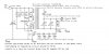
Is there a mistake in the circuit? The circuit is supposed to convert 5VDC to 500VDC.

Instead of 5 x 100V zener I used 2 x 200V and for D2 I used a HER208 as it was just for testing.

Thanks in advance!
 

Attachments

  • IMG_20170126_064943_099.jpg
    IMG_20170126_064943_099.jpg
    78.6 KB · Views: 115
Do you have access to an oscilloscope?
What are the voltages at T1 base and collector?
Are you using the exact transformer shown?
Have you tried reversing the polarity of the winding that drives T1 base?
 
Last edited:
Hi Alec.

Thanks for your reply. Unfortunately I do not have an oscilloscope. I use the exact same transformer. I will measure the voltage as soon as I get home.
 
I would agree with the polarity suggestion. Note that there are three input coils which must be connected the right way round.
If you have an inductance meter, the top two coils should be connected for maximum inductance. The base drive coil could be tried both way round.
 
Hi Duke.

Thank you for your reply. I do have an inductance meter and will measure the coil. I'm not sure if C4 might influence the reading but I could cut one leg off and solder it back after the reading. I did connect the two upper coils together.
 
Hi Alec.

I'm sorry for having missed your 3rd question. No, I have not yet tried to reverse the connection on the coil going to the transistor. I will try that to tonight.
 
Last edited:
Hi there.

I just measured the voltage on T1 and measured 4.827 between vcc and base and 4.634 between vcc and collector. I disconnected C4 and attempted to measure the inductance between pin 1 & 4 with the the 2 coils connected but was unable to get a reading, I tried 2 different inductance meters. I have yet to try to reverse the connection between the third coil leading to the transistors.
 
What are the voltages between T1 base and ground, and between T1 collector and ground?
Changing the R1 value may be helpful in getting oscillations started. Experiment.
 
Hi Alec.

Between ground and base I only measure 0,09 and nothing between ground and collector...

Which value for R1 would you suggest me to try? I do have a hertz function on my meter but I guess an oscilloscope would be better.

Is there also a paid service on the forum where I for example could offer to pay someone with more knowledge and equipment to build this for me for let's say 50 USD + materials?
 

(*steve*)

¡sǝpodᴉʇuɐ ǝɥʇ ɹɐǝɥd
Moderator
With the power off, measure the resistance between the collector and the +5V input. Then measure the resistance between the collector and ground.
 

(*steve*)

¡sǝpodᴉʇuɐ ǝɥʇ ɹɐǝɥd
Moderator
Is there also a paid service on the forum where I for example could offer to pay someone with more knowledge and equipment to build this for me for let's say 50 USD + materials?

Not that I'm aware of. Where did you get this circuit from? How confident are you that it works and is reasonably well designed?

Your measurements of voltage are inconsistent.
 

(*steve*)

¡sǝpodᴉʇuɐ ǝɥʇ ɹɐǝɥd
Moderator
OK, you've made a wiring error. The resistance from collector to +5V should be constant and much lower.

Check that you know which terminal the collector is. (It's the one without the arrow)

Also check that C4 is 47nF, not 47uF
 
Thanks Duke and Steve.

I desoldered the transformer and did an inductance reading and found out that the coils were not connected as I expected.

I expected one coil between pin 1 & 2, 3 & 4 and 5 & 6.

It turns out to be 1 & 6, 2 & 4 and 3 & 5.
1,978μH, 1,574μH, 1,733μH

I will do it on a breadboard this time :)
 
Use the fewest turns (2 & 4) for the feedback.
Connect the other two windings in series to give maximum inductance. (about 8μH?)
 
There is a winding giving about 2μH. There is another winding, not much different so you will get twice the number of turns. The inductance is proportional to the square of the number of turns so 2μH * 2^2 = 8μH. Could be considerably less than this if there is a lot of leakage inductance when the inductances just add.

I would be interested in the actual value.
 
The text says that the circuit resonates at about 55kHz with 147nF to tune it.
If my abacus is correct, the inductance is 70μH. This is a very large discrepancy from my other estimate.
 
Hi you all.

Just some quick feedback. Unfortunately I don't have much time this week to build and test. I did do a quick breadboard configuration. I didn't got any output but I measured around 8VAC on the transformer so I guess it's just a bad connection somewhere. I will have to find some more time during next week. I will probably do it on a veroboard again (I have 6 transformers and enough other components)

I will keep you posted.
 
Top