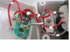
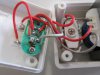
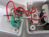
Maker Pro
Maker Pro

Is It A Transformer 220vac-110vac ?

hi guys,

i bought a transformer to get 110VAC of 220VAC,
what i got is a this product in the picture,

the coil has 3 wires,
all connected on same coil.
between 2 grey wires i have about 175 ohm,
between each grey wire to red wire i have 85 ohm and 73 ohm.

and it also have an A/B switch so you can change the input and output (220-110 to 110-220)

could this transfomator could do the job?
it look a little bit fishy....not?

thanks,
itai.
 

Attachments

  • trans1.JPG
    trans1.JPG
    64 KB · Views: 169
  • trans2.JPG
    trans2.JPG
    77.1 KB · Views: 141
  • trans3.JPG
    trans3.JPG
    75.6 KB · Views: 137
  • trans4.JPG
    trans4.JPG
    79.1 KB · Views: 154
Last edited by a moderator:

davenn

Moderator
hi there

having only 3 wires, I suspect it's an auto transformer ... ie there is no separate primary and secondary windings
just a single winding that is tapped and depending on the switch setting you can have 220-240 in 110 - 120 out or 110-120 in and 220 - 240 out
 
Yep, I think Dave nailed it.

I cannot be sure of the size since there is nothing to compare to, but it looks like maybe the transformer is 4 cm across. If it is this size, the power it can handle is pretty low, maybe 100W at most. What is it rated for?

Bob
 
Like Dave said it is an auto-transformer.
It will work but the build quality is horrible,it doesn't look like a safe device.
 
Like Dave said it is an auto-transformer.
It will work but the build quality is horrible,it doesn't look like a safe device.

i pretty agree that it isnt a safe one...
and probebly it is an automate one (like you and dave said)

but the fact is that its not functioning at all )-:

220VAC gets in,
220VAC gets out....

how can we explain that ?

and like bob mentioned,
it suppose to give 52W so i guess the size is ok?
(its is 4cm)
 
The explanation is somewhat strange.
It looks to me like it isn't wired properly !
Please verify this diagram I made.
With the N going directly from in to out not feeding the transformer it can't work.

trans3.JPG
 
dorke,
after you mention the wiring , i must mention that one of the wires was disconnected when i opened it,
it is showed with the yellow cycle on the picture (Wire G1 that you pointed)
i assumed it suppose to be connected where it is now,
but you say the N is the problem, not G1 ?
as i understand the diagram in your post is the actual wiring, not the ideal one ?!
 

Attachments

  • trans5.PNG
    trans5.PNG
    849.7 KB · Views: 115
Last edited:
Well just move wire G1 and connect it together with N.
It should solve the problem. like so:

trans3-modified.JPG
 
Last edited:
thanks again Dorke,
sorry for not mentioning this important thing in the begining.

i'll try it tonight.
(and also will try to understand the sense of it.)
you are awesome !!!!

by the way,
is there any way to make it more safe ?
like put some glue on it ? Epoxy ?

thanks,
itai.
 
that should fix it. WTG dorke.

Nameplate indicates transformer can operate with 70W load. That is dictated by temp rise in hotspot and assumes linear resistive load, not a light bulb, nor a motor or a bridge rectifier with large Cap load to a power amp. In these cases derate by 1/3 to 45W.

The brokn wire indicates a process design weakness. Hot glue or polyurethane tube adhesive over soldered wires to restrain from vibration and stress of closing it.
 
It will never be a truly safe device,but you can improve it a little:
1. Shorten the bare wires in the solder joints to minimum(now it looks like 2-3mm).
2. Re-solder without excessive solder(prevent does "humps").
3. Use RTV non-conductive sealant around and on the solder joints to glue and better isolate.
 
to further protect from line surge voltages of 3kv. add cct breaker and/or CLC line filter from power strip and 500V MOV

(so i still hadnt the time to fix it, hope tonight),
if the line in the wall is already connected to a CCT Breaker on the other side of the line - in the Electricity Cabin, so my situation is ok ? (is that what you meant?)
and i dont need also the CLC line filter....?

currently dont have an RTV like dorke suggests,
i will only fix the soldering to be as little as they could be.

thanks again fellows.
 

davenn

Moderator
note it is only rated at 70W ..... good for charging phones etc .... maybe an electric shaver low power things like that

keep that in mind if you do get it working
 
note it is only rated at 70W ..... good for charging phones etc .... maybe an electric shaver low power things like that

keep that in mind if you do get it working

it is for Wii (nintendo),
on the Wii it is labled that its need 52W.
i guess it a little more than charging phone or any other device....?!
 
(so i still hadnt the time to fix it, hope tonight),
if the line in the wall is already connected to a CCT Breaker on the other side of the line - in the Electricity Cabin, so my situation is ok ? (is that what you meant?)
and i dont need also the CLC line filter....?

currently dont have an RTV like dorke suggests,
i will only fix the soldering to be as little as they could be.

thanks again fellows.
if it broke once, it can also again. reconsider what I said
 
Top