Maker Pro
Maker Pro

Infocus projector no power

I will try and describe this the best I can, but I have a IN116 projector that has no power at all when plugged in (yes my power cable is fine) on the board when checking all the way to the bridge rectifier I have 164 VDC same for the primary to the first transformer. on the secondary side I have 5 VAC

Now it has a 2nd transformer near the outlet to the ballast or main control board I get the same 164VDC to the primary and nothing for the output on the secondary side.

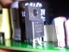
On the board mounted on the heatsink are 3 things..

D10XB60 bridge rectifier
K20A60U
FSU10A60

The wire that plugs into the ballast is saying 390V/0.64A on the board so I guess that's what the output voltage should be?

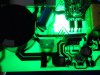
The power supply is the only thing wrong with this and if someone could help me pinpoint where in the circuit is the issue that would be great.

If you need any close ups of some areas of the board I can do that.
 

Attachments

  • DSC00652.jpg
    DSC00652.jpg
    135 KB · Views: 366
  • DSC00653.jpg
    DSC00653.jpg
    142.4 KB · Views: 467
  • DSC00654.jpg
    DSC00654.jpg
    132.9 KB · Views: 441
  • DSC00651.jpg
    DSC00651.jpg
    142 KB · Views: 648

(*steve*)

¡sǝpodᴉʇuɐ ǝɥʇ ɹɐǝɥd
Moderator
That's a switchmode power supply. Pretty much everything on that board is likely to me at mains potential (or should be treated as such) except for the top right corner (where there are two optocouplers, a high voltage capacitor, and a transformer separating the two sections).

So be careful.

SMPSs can be very difficult to fix. The fact that you're measuring the full rectified mains voltage across the primary side of the transformer on the right is a worry.

edit: after watching the video:

1) I wouldn't be poking around with my fingers like that.
2) the capacitor is rated for 450V, so 164V seems quite low.
3) The mosfet getting warm while nothing is happening seems like a warning sign. How warm?
4) I wonder if the first half of the board is PFC and whether it (is supposed to) step the input voltage up to around 400V
5) pictures of the reverse side of the board (where all the smarts are located) would be useful.
6) is it set for 220V rather than 110V?
 
Last edited:
That's a switchmode power supply. Pretty much everything on that board is likely to me at mains potential (or should be treated as such) except for the top right corner (where there are two optocouplers, a high voltage capacitor, and a transformer separating the two sections).

So be careful.

SMPSs can be very difficult to fix. The fact that you're measuring the full rectified mains voltage across the primary side of the transformer on the right is a worry.
The high voltage caps are the caps with the rubber covers? I really can't see what they are unless you are talking about the 150 uF 450v cap you see in the middle.

Also perhaps I did not check the transformer right? The transformer next to the capacitor in the middle the pins closest to the heatsink would be the primary side, no? i also heard you could check which side is what by using the ohm meter on each side and the primary would be the higher reading.
 
Sorry here is the back side it only has one voltage setting 120V

Also the part that gets warm is MR4010 I'm seeing temps of like 111F

And yes the first half is PFC, the chip is on the back and I checked for voltage to it when plugged in and I have nothing going to it. I can provide close ups of this area.

As you see on the board is silk printed what the output power to the main board should be, Since I have no power I don't get lights and the power button does not work in which it does not cause the lamp to strike.
 

Attachments

  • DSC00666.jpg
    DSC00666.jpg
    143.7 KB · Views: 384
  • DSC00667.jpg
    DSC00667.jpg
    149.6 KB · Views: 320
  • DSC00668.jpg
    DSC00668.jpg
    141.1 KB · Views: 536
  • DSC00670.jpg
    DSC00670.jpg
    152.8 KB · Views: 328
  • DSC00673.jpg
    DSC00673.jpg
    146.3 KB · Views: 313
  • DSC00672.jpg
    DSC00672.jpg
    132.4 KB · Views: 301
  • DSC00671.jpg
    DSC00671.jpg
    138.7 KB · Views: 334
  • DSC00669.jpg
    DSC00669.jpg
    142.1 KB · Views: 394
  • DSC00674.jpg
    DSC00674.jpg
    130.4 KB · Views: 291
  • DSC00675.jpg
    DSC00675.jpg
    131.2 KB · Views: 284
  • DSC00676.jpg
    DSC00676.jpg
    129 KB · Views: 280
  • DSC00677.jpg
    DSC00677.jpg
    136.2 KB · Views: 284
Last edited:
MR4010 might be the problem here.. between pins 5 & 9 Source & Drain I'm showing 33.44K the gate might be stuck, might explain why it gets up to 60C within 3 min and nothing else plugged into the board.


Thinking about it how it stays on 24/7 when plugged in a power spike could of taken it out
 

Attachments

  • MR4010.jpg
    MR4010.jpg
    111.3 KB · Views: 912

davenn

Moderator
it could be a fault in another part of the projector that is potting the power supply into a safty shutdown mode

Dave
 

davenn

Moderator
OK
so if its plugged into the rest of the system what voltages do you get ?
much PSU equip like that doesnt do much till it gets the appropriate signals from the micro processor

Dave
 
same voltages I got before 0V It lists clearly on the board what the standby voltage should be and the fact that only one isolator is seeing voltage (2.8V) and the other one is not then it's hard to figure out since I'm working on reverse engineering.
 

davenn

Moderator
OK

when I used to service projectors like that ... including the Infocus brand
it usually always required a board replacement as individual parts or service info would not be supplied :(

Dave
 
One question because I'm curious the transformer which is T201 on the board for the primary side I think it has 4 pins and the secondary side it has 6 pins.. how do you check to make sure it works?

If I'm checking right I seem to be having voltage going in on the primary but I need to be sure I'm checking the right pins.
 
LOL I've got these people saying the replacement chip (MR4010) I put in is wrong and that I have the source and drain put in wrong.. mind you they are just looking from the internet...

lol I told them the replacement chip heats up the same way the original did and I had the same voltages as before, but they said :rolleyes: next time show us the chip pins before you put it in..

Yeah ok.. I checked the pins which are forward and backwards before I took the original out.. It's between you and the company who designed the board.
 
Getting tired of looking at this in my closet, what power supply board similar that would work with this?

The board is marked output power 5V 0.15A 12V 3.6A
 

(*steve*)

¡sǝpodᴉʇuɐ ǝɥʇ ɹɐǝɥd
Moderator
Getting tired of looking at this in my closet, what power supply board similar that would work with this?

The board is marked output power 5V 0.15A 12V 3.6A

Assuming there are no other requirements, anything that can supply 5V at 0.15A or more AND 12V at 3.6A or more.
 
Yeah I figured that much.. I wish I knew which of the 9 pins carried the voltage so I could just manually power up the control board.

I'm reading this book here about SMPS assuming the output side is the one with 6 pins, all of them are showing shorted but I don't know if that's because it's in circuit?
 
I noticed something else.. so I've been reading this SMPS repair guide book by Jestine yong, anyways when checking the power IC I was checking VCC and ground on that but he says to check VCC on the IC and ground on the filter cap?
 
Top