Maker Pro
Maker Pro

Inductor coil question

Hey guys... New to the forum
After a quick explanation

I have a studio monitor (speaker) that fried a few components ..

I'm getting the replacements but a inductor coil is proving hard to find..

The circuit plan indicates that the coil is 25uh, that's the only info it has, the replacement that jaycar gave me is 47uh, is that going to be a problem, I feel as if it should match the specific plan as it's the power board for the amp
Cheers faderz
 

(*steve*)

¡sǝpodᴉʇuɐ ǝɥʇ ɹɐǝɥd
Moderator
A picture of the old inductor next to the new one would also be useful.
 
Also from what iv found is the 25uh 'general use' coil is not being made any more and the only ones I can find are bulk buys from the UK
 
Sir Faderz . . . . .

OK . . . . you initially had the majority of the mindsets here all keyed up and expecting some inductor related to speaker crossover networks passages and their bypass characteristics related to the adjunct capacitance being used.

That is . . . .until that meager 25 uh came to be mentioned..

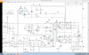
Turns out that it is being related to the switch mode power supply section of the unit.
Upon examining its left side lead and seeing it to be connected to C6 with its 390 ufd of solid power supply bypassing to ground.
Its right side lead is routed to the cold side of the primary of the main switch mode power transformer of the system. So you are getting 25 uh of filtered B+ isolation into the transformer.
Your new unit is giving even more . . . .47 uh . . . . than the design has specified.
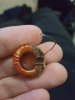
The new units wire size gauge is even GREATER ( current carrying capacity ) than the original, with its different inductor core permeability, even letting them use fewer turns.

Also from what iv found is the 25uh 'general use' coil is not being made any more

'course not . . . . .we uses 27 uh in these here modern times . . . .
(Your "vender / counterperson assistants" knowledge base must have fully qualified them as a peanut vendor at the ballpark.)

STARK REALITY . . .

I know that the 
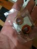
DARK amber "pookie" used on the bottom of the original is not being so visually and aesthetically appealing, but I would bet that your original L4 is STILL being just fine electrically.
It is just needing the side leads dressed and positioned and re tinned at the ends.

Appearance wise . . . give it a white base undercoat covering to then make the unsightly portion disappear, and then you make it really pop with an overpainting of slanting red and white peppermint stripes. OR . . . take yet another design statement by, instead, going for it ALL. . . . with the painting on of faux leopard spots !

73's de Edd
.....
 
Last edited:
The original looks pretty cooked, and one of its legs/pins has snapped off...

Would it be possible to use a 27uh in its place?
 

Attachments

  • 15320412209931455166177.jpg
    15320412209931455166177.jpg
    151.9 KB · Views: 27
The 27uH will be fine. The thicker wire makes it almost certain that it has higher current carrying capacity, which would be the only worry in a replacement, so you are covered there.

Bob
 

davenn

Moderator
The original looks pretty cooked, and one of its legs/pins has snapped off...

Would it be possible to use a 27uh in its place?


wow easiest thing to do would be to rewind it ... sort out the wire gauge > count the number of turns > cut off the old turns > clean off the cooked glue >
wind on the new wire > add a bit of glue to hold them in place

JOB DONE !

An even easier way would be to > leave coil intact > clean off the old glue > undo 1 turn on the shortened leg > reglue

JOB DONE !
 
The 27uH will be fine. The thicker wire makes it almost certain that it has higher current carrying capacity, which would be the only worry in a replacement, so you are covered there.

Bob


Would a 47uh be to much of a difference?
 

hevans1944

Hop - AC8NS
The new "replacement" inductor is 47 μH with 32 turns of wire on its core. Unwrap 15 turns, leaving 17 turns on the core, to bring the inductance down to about 25 μH. Spread those remaining 17 turns evenly around the circumference of the core using your fingernails. Cut to proper length, strip, and tin the lead you unwrapped.
 
Hop,

By my calculation it takes 23.34 turns to get 25 uH. The inductance is proportional to the square of the number of turns, so we get:

47 / 25 = 32^2 / n^2

n^2 = 32^2 * 25 / 47 = 544.7

n = sqrt(544.7) = 23.34

Bob
 

hevans1944

Hop - AC8NS
The inductance is proportional to the square of the number of turns
Ooops! A newbie mistake. Thanks for the correction, @BobK, 23 turns it is (can't do fractional turns with a toroid core IIRC). So the OP should unwind just 9 turns of the the 32 original turns and then space the remaining turns evenly around the core.

BTW, in the circuit shown 45 μH will probably work just fine.
 
Top