my teacher doesn't know much about electronics but is willing to get this circuit for a class project i am doing.
I have been building a constant power circuit to drive a motor on a solar powered car, and was after someone to have a look at it to see if there is any problems with its design.
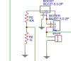
The circuit is powered by a 6ish watt solar panel being fed into an MPPT that outputs 12 volts. The circuit uses an arduino uno to control a buck converter that feeds the motor a constant amount of electrical energy. The output of the buck converter is shunted, the voltage drop from the shunt is amplified by the LM158 which in turn feeds into the arduino. Also the output voltage is measured by the arduino after being divided by 5.
Note- R6 should be 10k, had editing problems

I have been building a constant power circuit to drive a motor on a solar powered car, and was after someone to have a look at it to see if there is any problems with its design.
The circuit is powered by a 6ish watt solar panel being fed into an MPPT that outputs 12 volts. The circuit uses an arduino uno to control a buck converter that feeds the motor a constant amount of electrical energy. The output of the buck converter is shunted, the voltage drop from the shunt is amplified by the LM158 which in turn feeds into the arduino. Also the output voltage is measured by the arduino after being divided by 5.
Note- R6 should be 10k, had editing problems