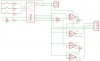
Hey guys, i am trying to figure out why this thing isn't working. I've had some boards made, and honestly if I have to make more, it's not a problem. Theoretically this should all be fine, but i can't seem to figure out why it isn't.
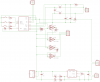
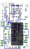
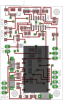
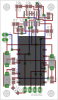
I've got the schematic from eagle and board file if that is gonna help. I managed to get a less complicated board working fine, and ill try and get schematics for the components and the circuits i used. It's gonna have to be later, as it's 3am here in australia. Any help is appreciated as i've been trying to get it working the last hour or so...
https://www.dropbox.com/sh/v6hi49gvwqbtv5q/AADBXZ-u1fhxDpK1UU_JYDGpa?dl=0
and those are the files