Maker Pro
Maker Pro

I need a voltage follower with >= 1Amp output for experiments

Status
Not open for further replies.
I want to do some experimentation with a 60v charger connected to 17x Lifepo4 cells in series.

The idea is the 2 resistor voltage divider will be connected across Battery Bank.
The voltage between resistors is Bank Voltage divided by number of cells.
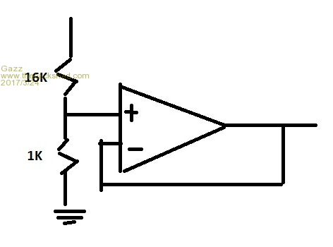
2017-03-24_161005_MrSquiggle.jpg

Shown are (16KΩ + 1KΩ) resistor values for 17 cell Bank
So the voltage between resistors is the equivalent of a single cells charge voltage.
The 1 17th voltage will follow voltage changes across the bank.

What would be the best IC or circuit for at least 1/1.5 Amp output.
 
Hi Steve,

The idea is to apply this 1 17th voltage to a single cell whilst it is connected in series on the bank charger.
Not sure if the follower could be powered by the Bank Charger, or how this would fit with options?
I thought the connection might be made with DPST relay, something robust.
 

(*steve*)

¡sǝpodᴉʇuɐ ǝɥʇ ɹɐǝɥd
Moderator
Then, do you just want a voltage regulator set to some sufficiently low voltage?

I think you're going to have to describe what it is you want to do rather than concentrate on how you think it can be done.

I fear that you may have in your head that you can use this 1/17th voltage to somehow allow a single cell charger to control the charge on your battery.
 
Fear not.

There is no set voltage, I am looking for the equivalent of Opp Amp Voltage Follower with higher current.
This is something I would like to build and own for different experiments.
 

(*steve*)

¡sǝpodᴉʇuɐ ǝɥʇ ɹɐǝɥd
Moderator
Just stick a couple of transistors to the output of the op-amp.

500px-Linear_amplifier_schematic.jpg

This is the basic circuit. Choose transistors which the op-amp can drive sufficiently to get the collector current you require.
 

(*steve*)

¡sǝpodᴉʇuɐ ǝɥʇ ɹɐǝɥd
Moderator
Ummmmm, because there's a transistor in there perhaps.

The transistors are connected as voltage followers too.

Do you understand how transistors work?
 
Thank you Bob, I am not here just to brag about what I know. Obviously :)
This rules out my next question, about putting the load between Transistors for source and sink.
 

(*steve*)

¡sǝpodᴉʇuɐ ǝɥʇ ɹɐǝɥd
Moderator
This rules out my next question, about putting the load between Transistors for source and sink.

This is a problem because as only one transistor is ever on, the would not be a path for current to flow. In addition to that it would be problematic as to where to connect the feedback loop.

The reason I asked if you knew how transistors worked is that it is kinda traditional to understand simple electronic components before you move up to more complex ones. So normally one would have a basic knowledge which would allow you to make sense of the added pair of transistors.

If you're self taught, you may have dived in without this basic knowledge, or without sufficient prior understanding.

One of the reasons this prior understanding is important is that you often use discrete transistors to increase the drive capability of things like op amps and even digital logic. The other reason is that you can often gain significant understanding about how an op amp will work in certain cases by looking at its own circuit diagram in the datasheet.
 
Hi Steve,

I am self taught, about 10 years ago I got a job as a Fumigator for Agricultural crops like potatoes.
A chemical that I later knew to be banned, got inside the space suit. Plus a pipe blew off into my face.
My short term memory is shot, so I relearn things over and over, write it down and move on.

Right now I am unemployed and not receiving any Government assistance.
I will not let this drag me down.
 
This is a problem because as only one transistor is ever on, the would not be a path for current to flow. In addition to that it would be problematic as to where to connect the feedback loop.

Yes, I can understand what you mean about the parallel feed loop.
Because you asked I was interested, will think on what you have said.

If this general idea of balance circuit could be applied??
More Opp Amps could be used to compare the cell against divisional voltage, for high cell gating.
How about another voltage follower for the other rail, or is the problem with transistors?
 
Last edited:

(*steve*)

¡sǝpodᴉʇuɐ ǝɥʇ ɹɐǝɥd
Moderator
I guess you need to consider if a new and more complex circuit is going to deliver benefits.

In this case, I'm not sure what problems you'd be solving, but the added complexity and uncertainty is fairly clear.
 
I guess you need to consider if a new and more complex circuit is going to deliver benefits.

In this case, I'm not sure what problems you'd be solving, but the added complexity and uncertainty is fairly clear.

Yes, the idea of a simple solution has run its race.
I have another discussion going about the choice of and protecting Opp Amp - input.
The price of cells compared to protection circuitry doesn't warrant re invention.

I have yet to study LTC3300
High Efficiency Bidirectional
Multicell Battery Balancer.

I am looking for a balancer that allows the Solar Controller to set charging voltage rather then balancer.
This might be an issue for commercial available systems, and I am yet to get any reply,
about the offered products suitability!

I have signed up to http://www.picaxeforum.co.uk Forum, but not yet approved.
Wanted to ask what is required for 17 channel "Shift Register?"
Not sure if that is right, but a 17 output counter with rest period between each high output in the cycle.
Hope that makes sense?
 
Last edited:
To make sense of why I am investigating, what we might call a "Bank division injector"?

The passive dissipative balance system do not work until cell is mostly charged.
Sellers confirm what I believed to be the case, with all such BMS I could find.

The question about Active Non-dissipative balance suitability has not been answered.
Unless a commercial system suits the specific requirement of "PSOC" controlled by Solar Charger,
there is the choice of paying for a custom design, or coming up with a DIY alternative!
 

(*steve*)

¡sǝpodᴉʇuɐ ǝɥʇ ɹɐǝɥd
Moderator
Have we changed topics?

I've seen only one balancing circuit that's not dissipative (it was for capacitors btw). It used inductors to pump energy from one capacitor to it's neighbor in order to level the voltage in adjacent capacitors.

For a BMS, unless you can transfer charge from one cell to another, it is counterproductive to do it at any other time than during charge, and then to simply prevent overcharge on any cells that happen to be reaching that point earlier than the others.
 
No, just describing the options.

I understand the charging properties of Lifepo4 way beyond the standard practices.\

Dissipative Balance is only possible when the cell is almost flat, or almost fully charged because it is voltage based.. the voltage of Lifepo4 doesn't change or vary enough between cells before it rises sharply at full charge or declines rapidly when almost flat.

This is only an issue if you intend to partially charge a cell, and not fully discharge, "PSOC"!.
Otherwise a Passive Balance with charge disconnect around 6.5 and discharge to 2.5V will work fine.
Although Voltage is not a good measure of cell capacity.

Not sure you have a full understanding, but yes, either way it has to be done while charging, or discharging depending on the method or requirements.

My earlier post was discussing if Active Balance curcuits were made to include the charge voltage and balance as part of the architecture.

After some reading, it appears the LTC3300 High Efficiency Bidirectional Multicell Battery Balancer is totally seperate to the Charge voltage level, other then High and Low Level Disconnect.

Now I know, the hunt begins for a commercial product using LTC3300, or I have contacts with a PCB manufacture who is open to new BMS for their customer base. If lucks on my side, you never know.
 
Last edited:
I have a question if someone can help.

As discussed, the concept being evaluated is a cell hopping cyclic injector.
A Voltage Divider outputs the Bank Voltage divided by the number of cells in series.

A 555 is connected to 17 output counter.
17 separate DPST relay connect to each of 17 cells.

The counter connects "cell 1" to the injector for several minutes,
then disconnects "cell 1" before connecting "cell 2".
Cycling around the cells, hopping one to the next.

33z6veh.jpg


In the scenario I am trying to simulate: The 17 cells are connected to solar charger.

The voltage across bank of 17 cells whilst connected to Solar Controller is 57.8V.
The Injector is 3.4V (Bank divided by number of cells).

How do I calculate what the voltage across cell would be with Injector connected.
For a cell with 3.3V across, connected in parallel with 3.4V injector.
And,
For a cell with 3.5V across, connected in parallel with 3.4V injector.

How would I approximate the new voltage equilibrium across connected cell,
to estimate effect?
 
Last edited:

(*steve*)

¡sǝpodᴉʇuɐ ǝɥʇ ɹɐǝɥd
Moderator
Firstly, I have no idea why the current average cell voltage is particularly meaningful.

Secondly, if this voltage is being generated from the battery pack itself, you have a significant isolation problem, not to mention one with physics. For this to have a chance of working, you must use a switch mode DC-DC converter or the current bring drawn from the cell will be (at best) slightly more than the charge current. The best you would achieve is discharging al but the target cell.

I'm going to investigate a few of these ICs you mention to give me a better idea of what they do.
 
Status
Not open for further replies.
Top