Maker Pro
Maker Pro

how to use analog sensor+ADC+pic16F877A

Hi guys..I'm still in progress learning about PIC16F877A and I'm just realize that I don't know how to configure analog input..I'm working on project that using analog distance sensor and output LED..when sensor detect something below 40 cm led will turn on..formula that I'm refer in datasheet is Vin * (1023/vref) and when sensor detect something in 40cm 0.7V current will flow to input pin..I'm using MPLAB C compiler..thank you :)
 
Thx steve..I already search it around..can i ask something..after setting adcon1 and adcon0 can I direct use the adc value to activate the output..or there need necessery c statement? I'm lost:confused:
 
There are a lot of tutorials on pic 16f877a availabe on internet..
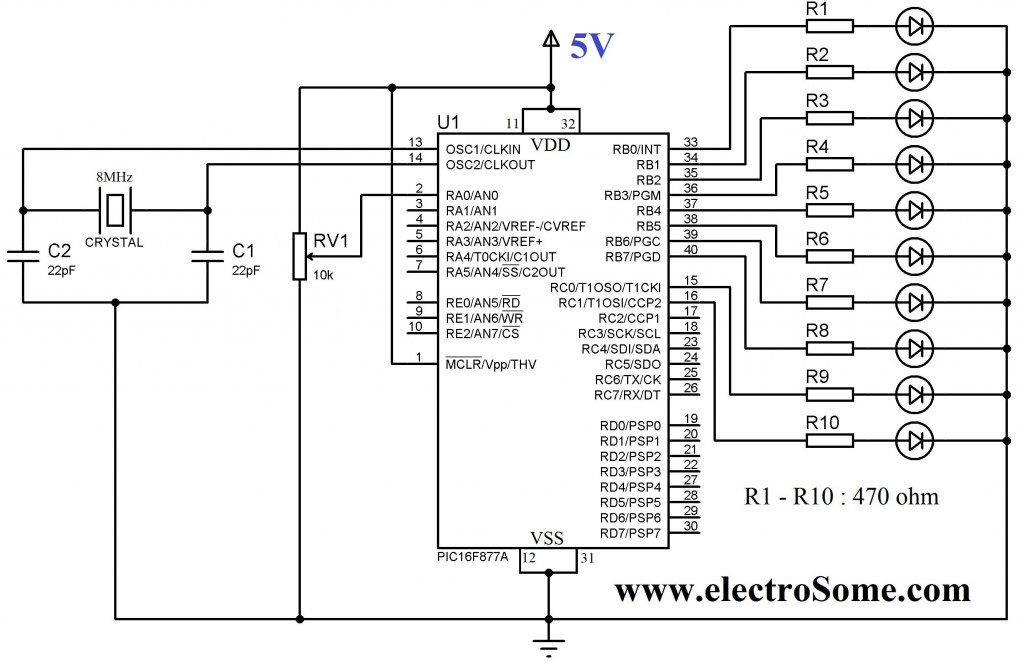
Using-Internal-ADC-Module-of-PIC-Microcontroller-1024x664.jpg

Code:
#include<htc.h>
#include<pic.h>

#define _XTAL_FREQ 8000000

void ADC_Init()
{
  ADCON0 = 0x41; //ADC Module Turned ON and Clock is selected
  ADCON1 = 0xC0; //All pins as Analog Input
                 //With reference voltages VDD and VSS
}

unsigned int ADC_Read(unsigned char channel)
{
  if(channel > 7) //If Invalid channel selected 
    return 0;     //Return 0

  ADCON0 &= 0xC5; //Clearing the Channel Selection Bits
  ADCON0 |= channel<<3; //Setting the required Bits
  __delay_ms(2); //Acquisition time to charge hold capacitor
  GO_nDONE = 1; //Initializes A/D Conversion
  while(GO_nDONE); //Wait for A/D Conversion to complete
  return ((ADRESH<<8)+ADRESL); //Returns Result
}

void main()
{
  unsigned int a;
  TRISB = 0x00; //PORTB as output
  TRISC = 0x00; //PORTC as output
  TRISA = 0xFF; //PORTA as input
  ADC_Init(); //Initializes ADC Module

  do
  {
    a = ADC_Read(4); //Reading Analog Channel 0
    PORTB = a; //Lower 8 bits to PORTB
    PORTC = a>>8; //Higher 2 bits to PORTC
    __delay_ms(100); //Delay
  }while(1); //Infinite Loop
}

Source:
Using ADC of PIC Microcontroller using Hi-Tech C
 
Top