Maker Pro
Maker Pro

How to test buzzer

Hi
My buzzer is not working I don't know why it's not working

Buzzer gnd ---- gnd
Buzzer VCC --- 5V
Buzzer S --- 5V

When I do above connection buzzer doesn't gives a sound?

I have attached photo of buzzer. Any help would be appreciate
 

Attachments

  • IMG_20201004_184909.jpg
    IMG_20201004_184909.jpg
    390.1 KB · Views: 12
  • IMG_20201004_184840.jpg
    IMG_20201004_184840.jpg
    175.2 KB · Views: 13

Harald Kapp

Moderator
Moderator
There are different types of buzzers:
  1. With integrated oscillator. These usually have two wires and start buzzing when a voltage is applied.
  2. Without integrated resistor, These require an external oscillator and have a third pin to allow creating the necessary feedback. From your photo I take it you have this kind of buzzer. It will not work on DC voltage without an oscillator.

Rad more about piezo buzzers e.g. here.

I have PIC18F45K80. I am using MPLABX 5.40 and XC8 2.30.

I have written code that supposed to sound the buzzer for 3 seconds and two seconds of silence and then repeat. When I Run code buzzer doesn't give any sound

Code:
#define _XTAL_FREQ 8000000
#include <xc.h>
// PIC18F45K80 Configuration Bit Settings
// 'C' source line config statements
// CONFIG1L
#pragma config RETEN = OFF      // VREG Sleep Enable bit (Ultra low-power regulator is Disabled (Controlled by REGSLP bit))
#pragma config INTOSCSEL = HIGH // LF-INTOSC Low-power Enable bit (LF-INTOSC in High-power mode during Sleep)
#pragma config SOSCSEL = HIGH   // SOSC Power Selection and mode Configuration bits (High Power SOSC circuit selected)
#pragma config XINST = OFF       // Extended Instruction Set (Enabled)
// CONFIG1H
#pragma config FOSC = INTIO2    // Oscillator (Internal RC oscillator)
#pragma config PLLCFG = OFF     // PLL x4 Enable bit (Disabled)
#pragma config FCMEN = OFF      // Fail-Safe Clock Monitor (Disabled)
#pragma config IESO = OFF       // Internal External Oscillator Switch Over Mode (Disabled)
// CONFIG2L
#pragma config PWRTEN = OFF     // Power Up Timer (Disabled)
#pragma config BOREN = SBORDIS  // Brown Out Detect (Enabled in hardware, SBOREN disabled)
#pragma config BORV = 3         // Brown-out Reset Voltage bits (1.8V)
#pragma config BORPWR = ZPBORMV // BORMV Power level (ZPBORMV instead of BORMV is selected)
// CONFIG2H
#pragma config WDTEN = OFF      // Watchdog Timer (WDT disabled in hardware; SWDTEN bit disabled)
#pragma config WDTPS = 1048576  // Watchdog Postscaler (1:1048576)
// CONFIG3H
#pragma config CANMX = PORTB    // ECAN Mux bit (ECAN TX and RX pins are located on RB2 and RB3, respectively)
#pragma config MSSPMSK = MSK7   // MSSP address masking (7 Bit address masking mode)
#pragma config MCLRE = ON       // Master Clear Enable (MCLR Enabled, RE3 Disabled)
// CONFIG4L
#pragma config STVREN = ON      // Stack Overflow Reset (Enabled)
#pragma config BBSIZ = BB2K     // Boot Block Size (2K word Boot Block size)
// CONFIG5L
#pragma config CP0 = OFF        // Code Protect 00800-01FFF (Disabled)
#pragma config CP1 = OFF        // Code Protect 02000-03FFF (Disabled)
#pragma config CP2 = OFF        // Code Protect 04000-05FFF (Disabled)
#pragma config CP3 = OFF        // Code Protect 06000-07FFF (Disabled)
// CONFIG5H
#pragma config CPB = OFF        // Code Protect Boot (Disabled)
#pragma config CPD = OFF        // Data EE Read Protect (Disabled)
// CONFIG6L
#pragma config WRT0 = OFF       // Table Write Protect 00800-01FFF (Disabled)
#pragma config WRT1 = OFF       // Table Write Protect 02000-03FFF (Disabled)
#pragma config WRT2 = OFF       // Table Write Protect 04000-05FFF (Disabled)
#pragma config WRT3 = OFF       // Table Write Protect 06000-07FFF (Disabled)
// CONFIG6H
#pragma config WRTC = OFF       // Config. Write Protect (Disabled)
#pragma config WRTB = OFF       // Table Write Protect Boot (Disabled)
#pragma config WRTD = OFF       // Data EE Write Protect (Disabled)
// CONFIG7L
#pragma config EBTR0 = OFF      // Table Read Protect 00800-01FFF (Disabled)
#pragma config EBTR1 = OFF      // Table Read Protect 02000-03FFF (Disabled)
#pragma config EBTR2 = OFF      // Table Read Protect 04000-05FFF (Disabled)
#pragma config EBTR3 = OFF      // Table Read Protect 06000-07FFF (Disabled)
// CONFIG7H
#pragma config EBTRB = OFF      // Table Read Protect Boot (Disabled)


void Port_pins_Initialized (void)
{
    LATA = LATB = LATC = LATD = LATE =  0;
    TRISA = 0b0000000;// all are output, Unused
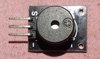
    TRISB = 0b0000000;// Buzzer connected to B0
    TRISC = 0b0000000;// all are output, Unused
    TRISD = 0b0000000;//
    TRISE = 0b0000000;// All are output, Unused
 
    ANCON0 = 0; // digital port
    ANCON1 = 0; // digital port
    CM1CON = 0; // Comparator off
    CM2CON = 0; // Comparator off
    ADCON0 = 0; // A/D conversion Disabled
}

void main(void)
{
  Port_pins_Initialized ();
 
    while (1)
    {
        LATBbits.LATB0 = 0;//Buzzer on
        __delay_ms(3000); // Wait for 3 seconds
        
        LATBbits.LATB0 = 1; //Buzzer off
        __delay_ms(2000);  // Wait for 2 seconds

    }
}
 

Harald Kapp

Moderator
Moderator
Your code applies DC to the buzzer (3 s on, 2 s off). This doesn't work, as explained. You'll need either:
  1. A buzzer suitable for DC (example)
  2. An external oscillator for your 3-wire buzzer (example)
  3. Replace the on-instruction
    LATBbits.LATB0 = 0;//Buzzer on
    __delay_ms(3000); // Wait for 3 seconds
    in your code by a call to a subroutine that generates an oscillating signal. When you apply an oscillating supply voltage to the "+" and "-" of the buzzer it will emit sound at the frequency of the oscillating supply.
 
No. That won't help.
It may be that your buzzer is a sort of speaker used for buzzers and that you need to give it a sound signal, an oscillation, instead of just on and off.
If your "buzzer" needs an oscillating signal, you can make this with the micro, the PIC, without the crystal.
Sorry, not a PIC person. Google PIC and buzzer?
I got this as the first hit. It seems to talk sense.
https://microcontrollerslab.com/active-passive-buzzer-interfacing-pic/

It seems similar to that suggested above, for the same reasons.
Read more about piezo buzzers e.g. here.


Can you tell us the type of buzzer you have, so we can check which sort it is.
 
Can you share a part number for the buzzer? Or a data sheet?
There is no part number on buzzer and board. I am struggling to get exact datasheet. That's why having problem

I have posted photo of module Take a look at photos. .
 
Last edited:

Harald Kapp

Moderator
Moderator
Unless you are able to tell us the specific type of your module all we can do is guess. @bertus found 2 modules. We are not even sure yours is one of them. Also, Bertus linked to 2 different versions. The passive one requires an oscillator (done in software in the code example on the linked website, as I stated in my post #5). Only the active one works without oscillator.
As your module doesn't work from DC only, I suppose it is of the passive type.
 

bertus

Moderator
Take a look at photos.
Saw them. :) Generally people buy such things, so they often have a link to the site that they got them from & with that a part number, or datasheet.
I understand that in your case they arrived by a method that provided no such part number. Got it.

People are working quite hard to try to help.
I suspect the answer to your issue has been posted a couple of times now.
The PIC can make an oscillating signal, with a program, that when applied to the "buzzer" will be turned into a sound. Follow carefully what the other guys are telling you and you'll have a workable solution. Let them know which bits you didn't understand and you;ll find them patient and helpful.
Enjoy.
 
If your "buzzer" needs an oscillating signal, you can make this with the micro, the PIC, without the crystal.
Can you explain how we generate a oscillating signal with a any micro for buzzer? Once I understand I can write code.

Pic18f45k80 has internal oscillator
 
Do you read our answers at all? As I stated in post #12 there's a code example in the link to the passive buzzer @bertus gave you in post #5.

I don't understand arduino code Can you help me to understand delay line

Code:
// define the pin we will connect to
int buzzer = 12 ;
 
void setup ()
{
  // set our pin to output mode
  pinMode (buzzer, OUTPUT) ;
}
 
 
void loop ()
{
  // loop through frequencies to generate alarm sound
  unsigned char i;
  while (1)
  {
    //Frequency 1
    for (i = 0; i <80; i++)
    {
      digitalWrite (buzzer, HIGH) ;
      delay (1) ;
      digitalWrite (buzzer, LOW) ;
      delay (1) ;
    }
    //Frequency 2
    for (i = 0; i <100; i++)
    {
      digitalWrite (buzzer, HIGH) ;
      delay (2) ;
      digitalWrite (buzzer, LOW) ;
      delay (2) ;
    }
  }
}

In the code there is two for loops one run 80 times and other for 100 times. In the loop we set buzzer pin at high state then gives delay and then set to low state

What does it say delay (2) ; Is it 2ms delay or 2us delay ?
 
Top