OK, that circuit isn't suitable for driving an Arduino input. Here's a circuit that is.

I've used a dual op-amp, the LM358, even though only one half is used. This is your most easily available option. You can't use a 741 here as BobK said because it's not a single-supply op-amp.
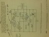
The op-amp is a simple buffer or voltage follower. R1, D1 and D2 clamp the voltage to slightly over 5V to prevent damage to the ADC in the Arduino. R2 loads the op-amp output to ensure it can get all the way down to 0V. C1 is a decoupling capacitor, needed to ensure reliable operation of U1, and should be connected as closely and directly as possible between pins 8 and 4 of the device.
The supply rail needs to be at least 8V for this circuit because the op-amp can't pull its output closer than a few volts below its positive supply. Modern op-amps can do a lot better, and if you use a "RRIO" (rail-to-rail input and output) op-amp, and you don't need the top and bottom few percent of the ADC range, you can power the circuit from 5V instead of 9V.
If you tell us even more about your project we can give more advice.