Maker Pro
Maker Pro

How is a brass gear removed from a DC motor?

Hi.
I have salvaged a 12 VDC motor from an old tyre-inflation compressor pump.
My plan is to replace the weak 3 VDC motor in my portable, rechargeable mini-vac for car with this 12 V motor, which can then plug directly into the cigar-lighter via the DC socket & 'run' switch.
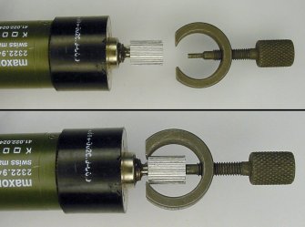
Both motors are identical dimensions, physically, except that old vac motor has no gear on the shaft, and old compressor motor does, which drove the cam via a secondary step-down gear.
The gear needs to come off, to allow the plastic fan to be pushed onto bare shaft.
Problem - I can't figure out how it comes off!
Tried pulling, levering, heating with a heat-gun to 'expand' it if press-fitted.
Even cut the gear in two, halfway along its length, thinking that a shorter piece may be easier to pull off. (Spun motor on 12 V while holding junior hacksaw then triangular file to cut & groove it).
Nothing doing.
As a last resort, if all else fails, would ferric chloride eat through the shaft?
(Suspect it is stainless steel).
I'm wary of 'etching' the gear away with Ferric Chloride, as if the solution 'wicks' into the motor's front-end bush, it may destroy the bush, especially if it is copper/brass material.
Alternatively, I'll spin the motor up again, this time using a flat file to 'lathe' the brass gear to shaft level.
Thanks, Clive.

12VDCmotor_A.jpg 12VDCmotor_A_zoom.jpg 12VDCmotor_B.jpg 12VDCmotor_B_zoom.jpg
 
Last edited:

Harald Kapp

Moderator
Moderator
The gear is likely press-fit or heat-shrunk onto the axle. Your heat gun may not generate enough energy to heat the parts sufficiently, puls it will heat gear and axle simultaneously, that is different from heating the gear and fitting it onto the cold axle.

You could try to remove the gear by using the motor as a lathe and grinding the gear away using a tool bit from a lathe or, lacking that, using a file, as you suggest at the end of your post.
 
Use a bearing/pulley removal tool such as this .........on a smaller scale obviously

A pair of pliers using the "cable cutter" section will work equally well.
Jaws sneak in between rear of the gear and the motor.

Key to success is a fine enough punch tool to fit inside the gear and suspend the motor/pliers combination over a set of vice jaws.
Oh...AND you'll need a small hammer and extra set of hands to boot. :cool:
 

Attachments

  • BearingClamp.jpg
    BearingClamp.jpg
    22.5 KB · Views: 0

Harald Kapp

Moderator
Moderator
The gear pullers are godd if there is space behind the gearwheel to get the clamps into. From Fuzzylogic's photos I take it that the gearwheel almost touches the motor housing., It will be difficult to get any sort (solid) of clamp in between gearwheel and housing, Unless there is enough clearance between axle and housing such that the gearwheel can be pulled forward far enough for clamps to grab behind it.
 
Thank you for helpful replies.
Now that I know definitely that the gear is press-fitted / heat-expanded onto the shaft (or axle), and not screwed onto a threaded axle, makes further work easier to plan.
Yes, the pinion gear is butted close to the bearing, making behind-the-gear shaft access impossible.
However, as I've already made a deep, v-shaped groove in the gear, I'll cut / grind a v-groove in a 40 mm x 4 mm piece of steel flat-bar.
Using @Bluejets 's idea of a bearing clamp, the "groovy" flat-bar will wedge snugly into the pinion gear's groove, the flat-bar being laid across open jaws of my bench-vice, motor housing suspended loosely between jaws.
For a striking "pin", I'll first tap a large nail from top, then maybe a small jeweler's screwdriver tapped in to finalize extraction.
I may also try my butane pencil-torch, if I can get it to work again..
Once extracted, I'll measure the RPM of both old (3 V) and new (12 V) motors, to compare fan speed.
When the compressor was run open, the offset cam and air-piston (which stripped it's seal-ring) moved at quite a high rate, so I guess the motor, which would be geared about 6:1, was spinning along at high revs.
I like the square-tube puller & pusher described in "Instructables", but will build those later, as for now, it's just this one extraction procedure.
 
Last edited:
Forget the heatgun. It will destroy the insulation on the armature if it already hasn't done so..
And ruin any oil lubricated plain bearing.

Use the bearing puller in the groove you have already made.
You can get nut spltters and it should be a doddle to split brass.
 
Sir FuZZ1L0G1C . . . . .


99 and 86 /100th's positive probability that your / that motor shaft is NOT going to be SS. ( As being confirmed by a rare earth "maggits" touching / proximity)

NO HEAT / FLAME application !

Looking at the very bottom photo, to my eye, it appears that the small frontal half of the already cut brass gear has already split and is showing the motor shaft. Thereby just a spreading being needed on that gear portion, to free it from encircling the motor shaft anymore..

No insertion clearance for the suggested "pullers".

IF being my nut to crack . . . and the supposition of a possible very, very slight scoring of the motor shaft logitudinally is being permissible.

I would use a Dremel tool mounted cut off wheel and pick points on the gear gaps 180 degrees apart and go down in those grooves alternatively, working between both sides.
A viewing of the motor shaft end , lets you initially guesstimate the depth of progress. At the point of catching the first glipmse of silver instead of brass, on the both halves created deeper grooves , stop and clamp two vise grip pliers on each of the brass halves and rotate a hard twist in opposite directions to each other . That should then let the porposefully extremely weakened gear halves pop apart.


Been using the " drill motor chucked work and mill file lathing " since I was 10 yrs old.
Invite 3 friends over and all of you take off your shoes, and then by finger and toe digital computation,you can figure how many years that has been.
If being LOOSELY lap held, its one fault seems to be "ovalation" / developed eccentricity of the rounding action, but that can be heavily minumized if the drill motor is mounted as to being immobile and one end of he file is also braced so as to be immobile. Then as the free end of the file is levered down. The sound of erratic contact points point out any eccentricity from true rounding . . . then you just concentrate on reducing down the high portion, untill a true roundness is attained.

73's de Edd . . . . .

If others are looking up to you for emulation amd stability, just be sure to hide, when you bite your nails.


Just now noticed that I had omitted one question.
Compare the pole counts of the two motors armatures, as to their being 2-3 or 4 poles.
In the air compressor application, the added torque of extra poles would come into play in attaining the heavy loaded grunt work of getting that final 30 PSI or so.
Whereas . . . in the case of the somewhat constant air loading of the air impeller of a vacuum cleaner, the MAX high speed of a screaming 2 pole motor would be a necessity.
Also, it's hard to visually judge, but what are the motor case outer dimensions ?
 
Last edited:
The tool could be more costly than a dozen motors,
Gear-puller.jpg

So destroy the bad gear with
smallnippers.jpg
 
Hi, apologies for the delayed reply - been so busy with other work I haven't had a chance yet to return to the above task.
Will update when work on it resumes..
 
Top