Maker Pro
Maker Pro

How can I bypass a switch on a humidifier?

I am building a temperature and humidity controlled chamber, however the humidifier I purchased has a standby function. This means that when the separate humidity sensor detects a humidity below range and sends power to the humidifier it doesn’t turn on. I have tried holding the button down but this turns on the light and not the power.

Is it possible to bypass the switch?

The switch as a number of functions:

Single short press: humidifier on
Second short press: intermittent humidifier
Long press: light on
Second long press: variable light

I do not require the light functions. The system does have an auto shut-off button if the humidifier runs out of water which would be great to maintain, but not essential.

Product details and images of the circuit board attached.

Any help would be greatly appreciated.
 

Attachments

  • image1.jpeg
    image1.jpeg
    67.2 KB · Views: 14
  • image2.jpeg
    image2.jpeg
    101.6 KB · Views: 14
  • image3.jpeg
    image3.jpeg
    92.4 KB · Views: 14
Hello. You provide with very little information. You could start with brand, model, the sensor you are using...
when the separate humidity sensor detects a humidity below range and sends power to the humidifier
mains power ?
I have tried holding the button down but this turns on the light and not the power.
Obviously it was not ment to be used that way.
I suspect that you may need to interface with the units microcontroller to be able to operate it the way you wish.

You could always use the humidifier as a standalone unit usig its internal sensor but i suppose you have your resons for not wanting to do this.
 

Harald Kapp

Moderator
Moderator
A single short press can be simulated by a monostable circuit using e.g. a 555 timer IC as shown in this article. The relay contacts are in parallel to the button on the humidifier to simulate the button press. Timing needs to be adjusted such that the on time of the relay is accepted by the humidifier as "single short press". Calculators for determining component values for 555 based timers can be found galore on the internet.
 

hevans1944

Hop - AC8NS
I am building a temperature and humidity controlled chamber
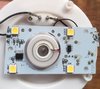
Since you are into building stuff, you might try "reverse engineering" that undocumented Chinese POS to make your own driver for the ultrasonic "mist transducer." This is a virtually impossible task for the neophyte builder because there is likely no information about the transducer or the microprocessor controlling it, which is likely labeled U1 on your image2. It is usual practice for the manufacturer to file off any identifying marks, plus you have no idea how it is programmed, even if you find out what it is. Then there is the multi-layer PCB, in the way of identifying how everything is connected. Good luck figuring that out.

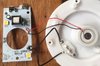
You gotta make all sorts of other stuff to control the temperature and humidity of your chamber, so why not make your own humidifier that works to your specification? All you need is that transducer from your Chinese humidifier and a driver, plus some "glue" circuitry to control everything. You were gonna ask us about the glue circuitry in another thread, right?o_O

Or follow @Harald Kapp's advice in his post #3, and simply parallel a set of relay contacts with the push-button switch on the Snow Mountain Humidifier. Problem with that is keeping track of the current state of the humidifier since that push-button has three "misting" modes: (1) first press turns on continuous mist, (2) second press turns on intermittent mist, (3) third press turns mist off. Sounds like, for your temperature and humidity controlled chamber, you just need on/off control.

One possible solution is to use the external humidity sensor, that provides power to the Chinese humidifier, as a "trigger" for a pair of 555 timers. The first timer is a delay timer to allow power to the humidifier to stabilize. The second timer is the "one shot" pulse, triggered when the first timer delay "times out," that you need to simulate pushing the button (once only!) when the Chinese humidifier is ready to accept it.

Then, if you do want to extend the button press functionality, it also has three LED illumination modes controlled by long presses of the push-button: (1) first long press turns on the LEDs, (2) second long press makes the LEDs "breathe" by presumably ramping their brightness up and down, (3) third long press turns off the LEDs. That all seems non-essential to your purpose and so can probably be ignored, as you mentioned in your first post.

We are curious as to what transducers you are using to sense temperature and humidity, and how these transducers are connected to control a heater and a humidifier. Will your chamber also include a fan to circulate the air inside of it? Will it have stainless steel walls to allow easy wipe-down and cleaning? Are you aware you can purchase such chambers in various sizes off the shelf at truly exorbitant cost?:D

I don't blame you for wanting to construct your own! Just be aware it can be a non-trivial task, depending on what specifications are attached to the temperature and humidity controls. Most common humidity sensors are slow to respond to changes in humidity, and may themselves be sensitive to temperature as well as humidity. The most accurate humidty sensor that I know of is a "chilled mirror" sensor. This consists of a thin first-surface mirror whose back side is cemented to a Peltier solid-state cooler, along with a temperature sensor that measures the front side (first surface) temperature. An LED or a laser diode shines on the mirror at an angle which reflects the light into a photoelectric cell. A control circuit lowers the temperature of the mirror until a film of dew sublimates onto the front-surface mirror. The dew disrupts and scatters the light reflecting off the mirror, causing the control circuit to allow the mirror temperature to increase and evaporate the dew. This is a negative feedback loop that oscillates closely around the dew-point temperature. It is a simple matter to convert the dew-point temperature into relative humidity given the temperature inside the chamber where the humidity sensor is located. Well, simple if everything is controlled by a microprocessor.:cool:
 
Last edited:
I am heartened that I am not a total simpleton in finding it hard to resolve this.

You were gonna ask us about the glue circuitry in another thread, right?o_O

You have piqued my interest, I will do some more digging but think that might be beyond me...

Or follow @Harald Kapp's advice in his post #3, and simply parallel a set of relay contacts with the push-button switch on the Snow Mountain Humidifier.

@Harald Kapp makes a very good suggestion and that video is very clear.

We are curious as to what transducers you are using to sense temperature and humidity, and how these transducers are connected to control a heater and a humidifier. Will your chamber also include a fan to circulate the air inside of it? Will it have stainless steel walls to allow easy wipe-down and cleaning? [/QUOTE]

I am using a couple of Inkbird plug and play sensors, picture attached. I have plugged a heatmat into the temperature sensor and the Snow Mountain humidifier into the humidity sensor. I am running the set up initially using a large styrofoam cool box, but I am working on a larger verusion....if i can get the trial to work. I am not intending to run a fan on this version but will need to on the larger chamber.
 

Attachments

  • IMG_5200.JPG
    IMG_5200.JPG
    235 KB · Views: 2
You provide with very little information. You could start with brand, model, the sensor you are using...mains power ?

The product information is included in the pictures img.1 It is a Snow Mountain Humidifer, mains power to a USB socket. Sensor is an inkbirdpug and play details on subsequent picture included in this thread.

Any suggestion on how best to interface with the units microcontroller? Or would you agree that @Harald Kapp and his 555 solution?

You could always use the humidifier as a standalone unit usig its internal sensor but i suppose you have your resons for not wanting to do this.

Unfortunately it does not have an integrated humidity sensor.
 
A single short press can be simulated by a monostable circuit using e.g. a 555 timer IC as shown in this article. The relay contacts are in parallel to the button on the humidifier to simulate the button press. Timing needs to be adjusted such that the on time of the relay is accepted by the humidifier as "single short press". Calculators for determining component values for 555 based timers can be found galore on the internet.

Thank you for this suggestion, I was looking at replacing the switch but this seems plausible and I am up for dusting off my soldering iron and getting into the weeds.
 
Top