Hi everyone, some help/discussion on this would be appreciated very much 
(TL;DR at bottom)
I have this pretty old (at least 10 years) Hitachi stereo that wasn't in use (I have better equipment as far as stereos/amps are concerned) but recently I've found myself in need of an inline volume control able to be adjusted remotely. I did a lot of shopping but it's a real pain to find anything that is good value and that won't take weeks to arrive (I'm in the UK and literally every single motorised pot version comes from Hong Kong/China).
So I dug it out to use as an inline volume control since it actually has a remote and receiver etc.
It actually does the job ok, besides a few moderate snags.
One being that it has a woofer output. I don't need that since I'm using it as an inline volume control and I don't want it messing with the audio in any way (besides volume lol) yet I'm pretty sure that when using the stereo the resulting output audio sounds less bassy (which I'm assuming is because the bass frequencies are being isolated to the woofer output - but I'm only using the red and black cable clips [not pictured]).
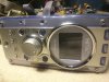
On top of that the woofer output jack (small red square) doesn't even work. It's dead. I can't tell where it might be broken and it's a lot of effort to go through just to fix a feature I don't need.
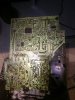
Here are some pics of the main circuit:

I think that the coil at the top (long red square) is to isolate the bass frequencies, much like a crossover circuit does. If I remove it and join the residual connections on the circuit together, would that solve my problem? Or is that silly thinking haha, it does sound like it.
The other issue is the LCD display's backlight is dying/dead. It connects at the point circled in green (I think - either that or the two pin port at the bottom right which says +4.5v -4.5v - one connects to the battery compartment). I heard that the capacitors are likely the problem. Anyone know which ones it may be? There is some brown sticky-looking solder joins (I don't think they are burn marks) - that where they have leaked?
Also (because learning), does anyone know what the (presumably) adjustment screws circled in blue might be for? Just curious.
Any tips or info/discussion anyone can share about this kind of work would be greatly appreciated, thanks
Sorry for the lengthy post and, thanks for reading
-----
TL;DR: Stereo appears to be not outputting low-end frequencies (due to "woofer out" - how do I have all the sound output from only the L/R jacks?) and the LCD backlight has died. Picture is the mainboard, how do I fix?
(TL;DR at bottom)
I have this pretty old (at least 10 years) Hitachi stereo that wasn't in use (I have better equipment as far as stereos/amps are concerned) but recently I've found myself in need of an inline volume control able to be adjusted remotely. I did a lot of shopping but it's a real pain to find anything that is good value and that won't take weeks to arrive (I'm in the UK and literally every single motorised pot version comes from Hong Kong/China).
So I dug it out to use as an inline volume control since it actually has a remote and receiver etc.
It actually does the job ok, besides a few moderate snags.
One being that it has a woofer output. I don't need that since I'm using it as an inline volume control and I don't want it messing with the audio in any way (besides volume lol) yet I'm pretty sure that when using the stereo the resulting output audio sounds less bassy (which I'm assuming is because the bass frequencies are being isolated to the woofer output - but I'm only using the red and black cable clips [not pictured]).
On top of that the woofer output jack (small red square) doesn't even work. It's dead. I can't tell where it might be broken and it's a lot of effort to go through just to fix a feature I don't need.
Here are some pics of the main circuit:
I think that the coil at the top (long red square) is to isolate the bass frequencies, much like a crossover circuit does. If I remove it and join the residual connections on the circuit together, would that solve my problem? Or is that silly thinking haha, it does sound like it.
The other issue is the LCD display's backlight is dying/dead. It connects at the point circled in green (I think - either that or the two pin port at the bottom right which says +4.5v -4.5v - one connects to the battery compartment). I heard that the capacitors are likely the problem. Anyone know which ones it may be? There is some brown sticky-looking solder joins (I don't think they are burn marks) - that where they have leaked?
Also (because learning), does anyone know what the (presumably) adjustment screws circled in blue might be for? Just curious.
Any tips or info/discussion anyone can share about this kind of work would be greatly appreciated, thanks
Sorry for the lengthy post and, thanks for reading
-----
TL;DR: Stereo appears to be not outputting low-end frequencies (due to "woofer out" - how do I have all the sound output from only the L/R jacks?) and the LCD backlight has died. Picture is the mainboard, how do I fix?
Last edited: