Maker Pro
Maker Pro

Help with N-Channel Mosfet as a switch at low voltages.

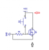
Hello all, I am working with a 2n7000 N-channel MOSFET and not getting the desired effect. I was expecting to use the fet to switch power to the rest of my circuit at 3VDC. I checked the data sheet and it says that my typical VGS(th) is 2.1 so at 3VDC I should be able to saturate the gate allowing the flow between Drain and Source to occur. When I connect the circuit as shown below by itself, no other circuit involved, with switch off, I get Vcc as expected between the arrows, but when S1 is closed, I only get ~2.1VDC between the arrows? I checked the RDS(on) and its about 1.8Ω so I didn't think that it should play much of a factor, what am I missing?


upload_2016-10-4_10-35-28.png
 

Attachments

  • upload_2016-10-4_10-34-31.png
    upload_2016-10-4_10-34-31.png
    420 bytes · Views: 95
  • upload_2016-10-4_10-34-40.png
    upload_2016-10-4_10-34-40.png
    18.2 KB · Views: 161
When on, your MOSFET is shorting the power supply!

Bob

Hi Bob, I neglected to mention that R1 is 1MΩ and that there was a load between Vcc and Q1's drain - I left it out for clarity because when I had the LED in, the circuit did indeed function, but when I tried to use the assembly to switch another load, I was not getting the 3V I needed to the rest of the circuit.
 
Okay. That's better.
It sounds like 3V is not enough to turn the MOSFET on fully.

I looked up the datasheet for it, and it is only characterized for on resistance at 4.5V, which means anything below that is undefined. The threshold voltage can be as high as 3V, which means it would only allow 250uA at that gate voltatge. You need a MOSFET that fully turns on at 3V.

Bob
 
Thanks Bob, I thought I was good with VGS(th) of 2.1, but as you mention, that was at a different voltage level and may not scale down. Thanks for the help, off to digikey to look for a solution.
 
Yes, that one looks good. They characterize the on resistance at even 1.8V (max 375mΩ) and it can handle 300mA at that gate voltage.

Bob
 
They characterize the on resistance at even 1.8V (max 375mΩ) and it can handle 300mA at that gate voltage.
Thanks Bob, how are you deriving 300mA for that particular voltage? I am still very leery of reading/interpreting transistor data sheets!
 
You might want to add the load device back into the schematic. Perhaps list some parameters for it. As Bob pointed out, the circuit as posted does not make sense. But thanks for posting an otherwise clear schematic!

Depending on your other requirements, you may have a good application for a bipolar transistor.

An ordinary NPN part can saturate pretty well with less than 1V on the base. And you may have one on hand, or at the corner store. Also, bipolar parts are more resistant to fatal damage from a little static. The very low voltage FETs are pretty easily zapped.

The requirement for base current will make your system less efficient; you might have a 10% - 20% increase in total Vcc current.

You would have to add a second resistor to set the base current. This resistor would go in series with the switch.

Ted
 
Also, bipolar parts are more resistant to fatal damage from a little static. The very low voltage FETs are pretty easily zapped.
Good point TedA! I didn't think of that :mad::(

I figured for a battery powered, small device, static wouldn't be an issue :oops:

I have some transistors, I will pick through them and see if any will meet the requirements for the circuit. BJT's annoy me, I never seem to have luck properly biasing them - once I learn how to make sense of the data sheet I am sure they will become more obvious.

Thanks for the input!
 
Top