Hello all of you!
I'm very new to the world of electronics, so i praise for your patience in helping me and making me understand what am i doing wrong in my project. Thanks in advance for your time.
So here it goes:
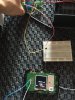
I have one 555 device that runs on 12v and i wish to "interface" it with another device (one hotspot) that i can only find 1.8v in two test pads.
What i need sounds fairly simple: when i switch the hotspot on i want it to connect to the 555 so that it activates a relay, that will light up some led light while the hotspot is on.
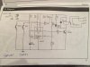
I've tried multiple things: 547npn transistor, connecting the base to the 1,8v with a resistor in the middle that in one simulation made it look like it would work, but it didn't. I don't know why.
I also tried to mess up with the control voltage from the 555 so that the comparator would be triggered by 1.8v instead of 12v but i also didn't had success with it.
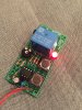
The 555 device is from velleman and i have the schematics from the simulation i was running with the transistor trying to act as trigger. I will upload that image, but i am open to any solution that is in the reach of my (low) capabilities.
Thank you
I'm very new to the world of electronics, so i praise for your patience in helping me and making me understand what am i doing wrong in my project. Thanks in advance for your time.
So here it goes:
I have one 555 device that runs on 12v and i wish to "interface" it with another device (one hotspot) that i can only find 1.8v in two test pads.
What i need sounds fairly simple: when i switch the hotspot on i want it to connect to the 555 so that it activates a relay, that will light up some led light while the hotspot is on.
I've tried multiple things: 547npn transistor, connecting the base to the 1,8v with a resistor in the middle that in one simulation made it look like it would work, but it didn't. I don't know why.
I also tried to mess up with the control voltage from the 555 so that the comparator would be triggered by 1.8v instead of 12v but i also didn't had success with it.
The 555 device is from velleman and i have the schematics from the simulation i was running with the transistor trying to act as trigger. I will upload that image, but i am open to any solution that is in the reach of my (low) capabilities.
Thank you

")