Maker Pro
Maker Pro

Help on understanding Omron G5V-1 12vdc relay

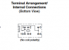
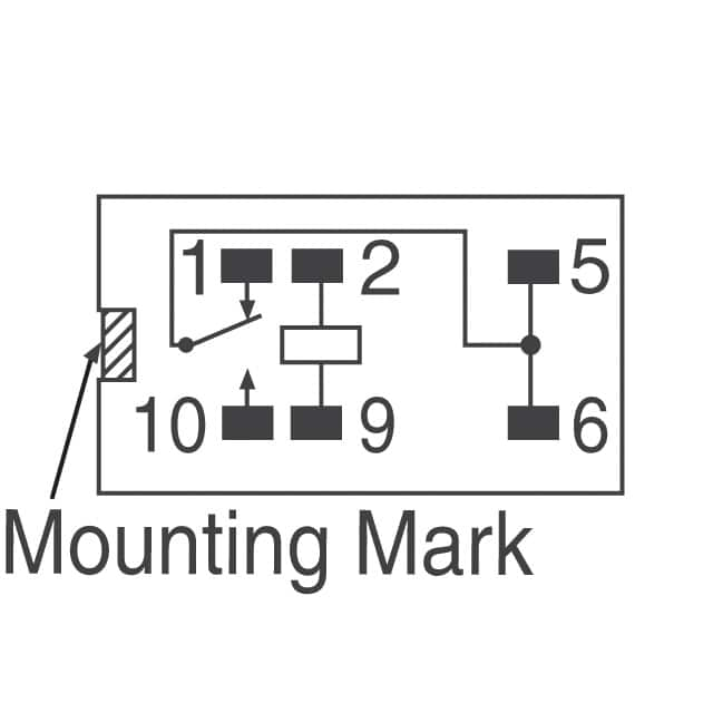
Is there someone who can explain how this relay works. It has six pins on it. What would you hook up to the various pins. I've enclosed the data sheet and a picture of the pin layout. I'm new at this and trying to learn. Thanks
 

Attachments

  • en-g5v_1[1].pdf
    873.3 KB · Views: 101
  • g5v-1 picture.png
    g5v-1 picture.png
    8.8 KB · Views: 274

Harald Kapp

Moderator
Moderator
The coil is between pins 2 <>9.
The common contact is shared on pins 5+6 (both are internally connected).
Pin 1 is the normally closed contact. When the coil is not energized, pin 1 is connected to Pins 6+6.
Pin 10 is the normally open contact. When the coil is energized, pin 10 is connected to Pins 6+6.

The general operation of relays is described e.g. here.
 
Schematic would look something like this.
upload_2018-2-2_13-13-44.png
Omron%20C1-v1.jpg
 
The part that moves between the contacts and is attracted by the coil is called the Armature, pins 5 & 6 are the armature common.
M.
 
If mounting on a circuit board i would solder one of the coil contacts to ground and the other coil contact would be voltage coming in to activate the coil. Pins 5 and 6 would be the source coming in to be switched to either pin 1 or pin 10. Is this correct?
 
Yes, 2 & 9 are the coil, pin 1 is the normally close (N.C.), pin 10 is the N.O.
If using it in a sensitive environment, it is wise to wire a reverse biased rectifier across the coil.
Google BEMF diode.
M.
 
Top