Looking at a application note from Microchip HERE. It details how one could calculate the maximum power from the PV cell by utilising a buck converter with current and voltage feedbacks to adjust the the PV's load.
I'm trying to adopt this to make a 12V Lead Acid Battery charger, but I'm having difficulty understanding the how/what/why of a couple areas in the schematic.
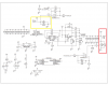
Schematic rotated and attached as PNG (Easier to read, and has my references)
Two questions:
1. In the red box, we see the regulated output (Vout) pin (which I assume goes to the battery), and then the J2-OUT header... What is J2-OUT? If it's closed circuit then it essentially feeds the whole Vout to ground via shunt resistors R5 and R6 (Which, granted, would allow the OpAmp to measure maximum output current) - but what purpose is that when we're trying to charge a battery? Is this jumper designed to be a momentary thing?
2. Yellow box; J1-VPV makes no sense to me. If we close circuit it, it would essentially short circuit the PV cell... Again we could read the current value - but for what purpose?
Shouldn't these shunts be in-line with the load? IE. Measure between the +ve of the PV cell and the buck, and between the Vout and the battery?
Can someone please help explain?
Thanks in advance.
-KB
I'm trying to adopt this to make a 12V Lead Acid Battery charger, but I'm having difficulty understanding the how/what/why of a couple areas in the schematic.
Schematic rotated and attached as PNG (Easier to read, and has my references)
Two questions:
1. In the red box, we see the regulated output (Vout) pin (which I assume goes to the battery), and then the J2-OUT header... What is J2-OUT? If it's closed circuit then it essentially feeds the whole Vout to ground via shunt resistors R5 and R6 (Which, granted, would allow the OpAmp to measure maximum output current) - but what purpose is that when we're trying to charge a battery? Is this jumper designed to be a momentary thing?
2. Yellow box; J1-VPV makes no sense to me. If we close circuit it, it would essentially short circuit the PV cell... Again we could read the current value - but for what purpose?
Shouldn't these shunts be in-line with the load? IE. Measure between the +ve of the PV cell and the buck, and between the Vout and the battery?
Can someone please help explain?
Thanks in advance.
-KB