Maker Pro
Maker Pro

Garmin gps 60cx gpsmap

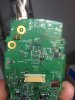
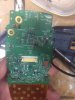
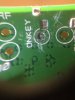
Hello all, I have not posted much, so bear with me. I have a Garmin 60cx gpsmap I bought on Ebay, saying that there was a problem with the power button,when I got it, I turned it on, but it only turned on every once in a while. So my intention was to replace this broken switch, but when I put my soldering iron to it, the copper pad came off, it is a double sided circuit board. companies I have contacted said it will cost at least $100, but I bought it for about $60. I am wondering if I could somehow find the next component in the circuit and run a wire from that? The problem with that idea is that the copper pad has been taken off, and I am not sure how to find the lead as it is a double sided board. I am willing to do a little micro soldering if I need to, but I mostly would like to find the component leading to that pad, and just run a wire to the switch from that.

Please tell me if this is confusing or I need to provide further detail.

[MOD NOTE: deleted all the poor pix]
 

Attachments

  • 20180314_202307796_iOS.jpg
    20180314_202307796_iOS.jpg
    276.9 KB · Views: 106
  • 20180314_202411048_iOS.jpg
    20180314_202411048_iOS.jpg
    284.2 KB · Views: 97
  • 20180314_205814334_iOS.jpg
    20180314_205814334_iOS.jpg
    264.1 KB · Views: 85
Last edited by a moderator:
If the (missing) pad isn't part of a thru' hole then it won't be connected to any interlayers of the pcb - which is a good thing.

What you don't show is the reverse of the board - we need to see a CLEAR and IN FOCUS image of the area around the damaged board and on both sides.
 
Great. Tell me if more images are needed.
 

Attachments

  • DSC01583.JPG
    DSC01583.JPG
    321.3 KB · Views: 50
  • DSC01583_LI.jpg
    DSC01583_LI.jpg
    322.9 KB · Views: 50
  • DSC01585.JPG
    DSC01585.JPG
    226.1 KB · Views: 72
  • DSC01593.JPG
    DSC01593.JPG
    173.5 KB · Views: 44
  • DSC01596.JPG
    DSC01596.JPG
    393.2 KB · Views: 33
  • DSC01596_LI.jpg
    DSC01596_LI.jpg
    394.5 KB · Views: 48
  • DSC01597.JPG
    DSC01597.JPG
    202.1 KB · Views: 54
  • DSC01598.JPG
    DSC01598.JPG
    369.3 KB · Views: 40
  • DSC01598_LI.jpg
    DSC01598_LI.jpg
    373.1 KB · Views: 45
  • DSC01599.JPG
    DSC01599.JPG
    419.6 KB · Views: 49
  • DSC01600.JPG
    DSC01600.JPG
    390.6 KB · Views: 45
  • IMG_1534.jpg
    IMG_1534.jpg
    417.9 KB · Views: 40
  • IMG_1535.jpg
    IMG_1535.jpg
    381.6 KB · Views: 40
  • IMG_1536.jpg
    IMG_1536.jpg
    317.4 KB · Views: 31
They could be 'filled vias' (given that I can't see any other actual thru-holes on the board) in which case you're stuffed. I can't see any traces to/from that isolated pad - as was - so must assume that it was a filled via and that the trace has been irreparably destroyed.....

It's more than double-sided too - I'd reckon on at least four layers.

I also think you'd have had trouble with the RF side given the corrosion at the antenna circuitry.

If you'd been UK-based I'd have sent you a handheld Garmin I have in my 'scrap box' for free......
 
OK, so if that original trace is gone, what about the idea of running a wire from the previous component, and connecting a switch to that component, if that makes sense? The only problem I can think of with that is finding the component. Do you have any ideas on how to do that?

Also, thank you for the generous offer. If you are willing, you could use Ebay with offer only and I could pay shipping and handling fees.
 
You need an electrical connection to 'probe' and use a continuity tester to find where that trace leads to/from - try cleaning the area around the pad labelled 'onkey' and looking for any copper to take a test point from. Without one you simply can't guess.

The most obvious solution would be to obtain the full board schematic/layout. Not sure if that's readily available. Searching Google shows many others requesting the same but with no answers.
OK, thank you for the info, I decided it is probably a little out of my league, and I ordered a cheap 60cSx board with corroded battery pads, hopefully that will be easier than this.
 
Top