Hi all !
Before starting, my apologies for this long post (and for potential English errors)")
The context (you can skip) : I'm continuing to get things ready to work on home automation process. And as I will be us ing my soldering iron a lot I first plan to build myself a little fan to suck out the emanations from the stain wires. Aside from the fan part which is fairly easy to build (battery, switch, fan, 3D printed case), I'm also working on the design of a small circuit which will serve as a battery charger, so I'll be able to use batteries for the fan and the many other things. The goal is to have a quick charger that supports many voltage and capacity of batteries, but that will go after. First, I'm focusing on a "simple" charger for a single cell battery, at 400mAh.
I decided to use the BQ2054 from Texas instruments for 3 main reasons :
- It is provided as a DIP package (among others)
- It contains all the necessary controls to ensure the security and correct charge of the battery
- The voltage and current of charge is programmable
Here is a link to the datasheet : https://www.ti.com/lit/gpn/bq2054
So. I started to design a simple circuit that would support fast charge for a single cell Li-On battery at a capacity of 400mAh (so, 4.2V of charge @ 400mA). Here is a schematic at my current state of design (click to enlarge):

All explain here why the choice of these components, and why.
If you're still here, thanks again for your patience, I understand that though I have some good theory basics on electronics I still lack a lot of knowledge and practice (forget about my project log, I was on the highest point of the Dunning-Kruger curve). However I am confident that I will understand your answer and will be able to learn new things and put them into practice. As Li-On battery charging is dangerous I moreover need to be twice more cautious.
Before starting, my apologies for this long post (and for potential English errors)
The context (you can skip) : I'm continuing to get things ready to work on home automation process. And as I will be us ing my soldering iron a lot I first plan to build myself a little fan to suck out the emanations from the stain wires. Aside from the fan part which is fairly easy to build (battery, switch, fan, 3D printed case), I'm also working on the design of a small circuit which will serve as a battery charger, so I'll be able to use batteries for the fan and the many other things. The goal is to have a quick charger that supports many voltage and capacity of batteries, but that will go after. First, I'm focusing on a "simple" charger for a single cell battery, at 400mAh.
I decided to use the BQ2054 from Texas instruments for 3 main reasons :
- It is provided as a DIP package (among others)
- It contains all the necessary controls to ensure the security and correct charge of the battery
- The voltage and current of charge is programmable
Here is a link to the datasheet : https://www.ti.com/lit/gpn/bq2054
So. I started to design a simple circuit that would support fast charge for a single cell Li-On battery at a capacity of 400mAh (so, 4.2V of charge @ 400mA). Here is a schematic at my current state of design (click to enlarge):
All explain here why the choice of these components, and why.
- DSEL/LED2, LED1, LED3 and LCOM : easy and quick. I just followed the datasheet and chose to pull down DSEL to ground to enter display mode 1
- ITERM : set to ground to end charge when current is less than 10% of the charge current
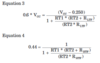
- On the left, RB1 and RB2 are a part of the voltage divider bridge used to allow the chip to sense voltage across the battery using pin BAT and regulate it. These resistors are set so battery charge voltage is set to 4.2V (for a single cell 3.7 Li-on battery)
- RSNS is the resistor used to sense current inside the battery through the SNS pin and control it. The value is chosen to have a max current of 400mA
- RT1 and RT2 are for the temperature sensor, a NTP thermistor with R25 = 10kOhms. With the help of one of yours, I was able to find the values for the temperature range I wanted (0°C - 40°C) and then compute RT1 and RT2, although it was a bit of pain as I am a bad player at functions maths (shame on me, moreover I'm a rendering programmer...) Anyway, got them to these unusual values. I will use parallel resistors to make them of course.
- C1 is connected to the TPWM pin. I used the suggested value, to have a frequency for the PWM signal at pin MOD of 100kHz.
- Just a concern about the RSMS resistor. The datasheet states, page 6, that the formulae used to compute RSNS is : Imax = 0.25V / RSNS. As no units are provided, I consider that IMax shall be in A, anr RSNS in Ohms. But using this, I end up with a resistor of only 0.625Ohms, and I find this value very low... Shall I use mA instead of A ?
- For ICOMP and VCOMP, the datasheet says very little about these. On page 9, it states : "To prevent oscillation in the voltage and current controlloops, frequency compensation networks (C or R-C) are typically required on the VCOMP and ICOMP pins (respectively).". I asked my friend Google about frequency compensation network, but what I found concerns OP-Amps only and use 2 pins (to have a resistor in series and a capacitor in parallel. Here I have only one pin to connect the network to, and I have no Idea of the frequencies implied nor on how to add the capacitor and potentially the resistor. Is the frequency the same used by the PWM modulator (setup to 100kHz)
- The MOD pin... I understand that it provided and PWM signal so I can use sort of a power transistor (e.g. a MOSFET) to provide the current in order to actually charge the battery. But I have no idea of the kind of circuit I have to put around the source and the drain of the MOSFET. Do I have to provide a specific voltage ? Limit the current by using resistors ? etc ? Or is OK if I just add a simple regulated 5V source (the same I use to power the IC)? e.g. if I connect the charger to an USB port, it would have enough power to charge the battery @ 400mA + power the IC.
If you're still here, thanks again for your patience, I understand that though I have some good theory basics on electronics I still lack a lot of knowledge and practice (forget about my project log, I was on the highest point of the Dunning-Kruger curve
). However I am confident that I will understand your answer and will be able to learn new things and put them into practice. As Li-On battery charging is dangerous I moreover need to be twice more cautious.