Maker Pro
Maker Pro

FAN5345

Yes a simple switch will be able to drive the pin 4, but as suggested by Steve, better to let the pin unconnected in order first start at full brightness.
 
Okay I've tried reconnecting pin 4 to the switch and leave just one LED on board. It lit up. But pressing the switch doesn't dim it.
 
OK, but we have a simpler setup to work with. Can you post a sharp picture of the small PCB ?
Are you aware of the pin numbering not like on any of the datasheet schematics but like on the pin configuration paragraph (just in case) ?
 

KrisBlueNZ

Sadly passed away in 2015
As Steve said, I would be concerned about that inductor. It looks pretty small, and 1 ohm resistance is pretty high for such a small inductance. I think it's just a signal inductor for noise suppression in medium- to high-impedance applications. Try using one that's rated for at least 1A such as http://www.digikey.com/product-detail/en/RLB0712-100KL/RLB0712-100KL-ND/2561284

I would also use a piece of stripboard or some other solder-based prototyping board, and minimise lead lengths, for all of the switching circuitry at least, instead of breadboard.
 
I'd like to ask something about these values:
-----------------------------------------------------------------------------------------

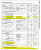
EN Low Time for Dimming = 0.5us (min), 300us (max)

Delay Between Steps = 0.5us (min), 300us (max)

EN Low, Shutdown Pulse Width = 1ms (max)


Maximum Boost Duty Cycle = 85%
Minimum Boost Duty Cycle = 20%
------------------------------------------------------------------------------------------


Can this be achieved by connecting a switch directly to EN? Thanks.
 
By the way, here's the electrical specification sheet of FAN5345.
 

Attachments

  • electrical specification sheet _fan5345.png
    electrical specification sheet _fan5345.png
    92.5 KB · Views: 108
Top