Maker Pro
Maker Pro

Diode Characteristic Graph

Hi,

I have a question on my course which is:

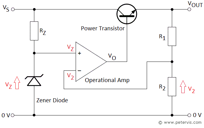
1) FIGURE 3 (on page 7) shows a PIR (passive infra-red) detector and its associated amplifier, as used in burglar alarm systems1.

a. The detector is powered from a 12 V unregulated supply that needs to be stepped down to 5 V. Design a suitable 12-to-5 V voltage converter using an op-amp and a diode that has the forward characteristics given in FIGURE 3(b).

I have designed a shunt regulator using an op-amp and a transistor which works when I simulate it. I can vary my R values in the potential divider element and change the diode sizes to multiple combinations which all give me the 12 to 5V regulation.

What I am struggling with is what the graph below is actually telling me, and how I relate this information to selecting a diode size?

fig 3b pag 7.jpg

fig 3a  pag 7.jpg

Thanks,

Moderators note : uploaded pictues to the forum as the direct linking did not work
Please upload to the forum in stead of trying to link next time

The complete question is on this page:
https://www.chegg.com/homework-help...associated-amplifier-used-burglar-a-q25446280
 
Last edited by a moderator:
The graph is telling you what the relationship is between the current through a particular diode and the voltage across the diode.
To answer the question set you have to use that particular diode, so there is no 'changing diode sizes' or 'selecting a diode size'.
 
The graph is telling you what the relationship is between the current through a particular diode and the voltage across the diode.
To answer the question set you have to use that particular diode, so there is no 'changing diode sizes' or 'selecting a diode size'.

Hi - Thanks, what I don't understand though is how that graph is telling me the diode size?
 
Unless you know what the diode's construction is and semiconductor is (germanium, silicon, .....?) I don't see how it could give any clue as to size. Why do you want to know the size?
 

Harald Kapp

Moderator
Moderator
What I am struggling with is what the graph below is actually telling me, and how I relate this information to selecting a diode size?
The graph tells you the voltage drop across the diode for a particular current through the diode, as others have stated before.
When it comes to diode size you probably want to select a diode according to the maximum permissible power dissipation which is also a parameter you'll find in the datasheet of the diode but not from this graph. No single graph can describe all parameters of a diode, that's why you find many graphs in a datasheet, one for each relevant parameter combination.
I have designed a shunt regulator using an op-amp and a transistor which works when I simulate it.
It would be helpful if you shared your design with us so you can receive useful comments on it.
 
It would be helpful if you shared your design with us so you can receive useful comments on it.

Without trying to sound ungrateful for the help, it isn't the circuit design I am struggling with. I have a circuit which works - perhaps by chance?! But what I am struggling with is that the question has asked me to use a diode which is characteristic of the information in the graph, but I am unsure how to relate this to diode selection.

My circuit design is below, it will work with the following configurations:

R1 = 5k
R2 = 8k
D1 = 3.1V

R1 = 8k
R2 = 9.2k
D1 = 2.7V

I'm sure I can find other combinations which work, but none of what I am doing is utilising the graph like the question is asking me to. I'm just not sure what to do with that information. I have no information on the load being applied, or the current requirements. Which is also making specifying Rs tricky.

My Dropbox link but won't work:
https://www.dropbox.com/s/n1orw7f7tbelhxy/Circuit.png?dl=0
Circuit.png


Online example of my circuit

voltage-regulator-using-op-amp-and-transistor-circuit.gif


Thanks
 
You're not being asked to build the circuit; just to design it. So diode selection shouldn't be an issue.
Considering the graph linearity, that particular diode could be substituted by a resistor if the current is kept within the graph limits.
 
Last edited:
You're not being asked to build the circuit; just to design it. So diode selection shouldn't be an issue.

Then why am I being asked to use a diode as per the graph if I'm not supposed to be selecting component sizes?

What I am getting at is... the question infers "use the graph" in my answer, but I am not using the graph because I don't understand how to relate the information of the graph to my answer. Unless the graph is a red herring in terms of answering the question?

Thanks
 
Then why am I being asked to use a diode as per the graph if I'm not supposed to be selecting component sizes?
That is the challenge; to consider how you could use the hypothetical characteristic shown to get 12V down to 5V.
 
That is the challenge; to consider how you could use the hypothetical characteristic shown to get 12V down to 5V.

As implied by the question and understood but, as mentioned, this is where I am totally stuck and looking for some assistance...
 
Unless we're missing some hidden background to the question there are no limits placed on how or where in the circuit that diode must be used. Clearly, from the graph, it is unsuitable as a reference voltage source, so an alternative, such as a Zener (which you've already tried), would be needed.
Personally I think the question has been poorly set, unless it was intended as a trick one.
 

Harald Kapp

Moderator
Moderator
Considering the graph linearity, that particular diode could be substituted by a resistor if the current is kept within the graph limits.
I agree with @cps13 that this would not fulfill the task description.
Online example of my circuit
The example uses a zener diode. You do not have one, What you do have is a Schottky diode (I assume that from the low voltage). It rally behaves like a resistor within the range shown in the graph.
Anyway, here'Äs one way how to use the diode within a crude voltage regulator:

Use a single diode in pass direction (anode to '+') with a current limiting resistor such that the voltage across and current through the diode are within the range of the diagram. Use an opamp error amplifier as shown in the example you used to regulate the output of the power transistor.
Since instead of a zener voltage you are using the diode's forward voltage, you have no regulation of fluctuations in the input voltage: any change in input voltage will change the current through the diode's series resistor and thus the output voltage. But as far as I can see this is the best you can do using a diode with this characteristic.
 
It really behaves like a resistor within the range shown in the graph.
That was my intended meaning in post #8.
But as far as I can see this is the best you can do using a diode with this characteristic.
Agreed. That arrangement is probably what the question-setter intended, but within the strict wording of the question the diode could be 'used' merely as, for example, a dummy load and play no part in the regulation. It seems to be a modern trend in academia to set questions which are imprecise, ambiguous or downright wrong :rolleyes:.
 
As an aside, here's the LTspice simulation of an interesting circuit similar to a voltage reference circuit I saw many years ago (I think in EDN).
It uses the amplified reference voltage to bias the reference source current (sort of a bootstrap), which stabilizes it with respect to input voltage variations.
This is similar to using a constant-current to bias the source.

In this case I used a Schottky diode for the reference, biased at 1mA.
The output voltage stability is thus determined mainly by the temperature sensitivity of the diode.
(Note that its forward voltage is less than the value in the TS's graph at that current.)

R4 is used to kick-start the circuit.

The output (yellow trace) changes little with an input voltage variation of about 7V to 15V.
(The simulation shows about 200µV)

Determining the op amp gain to get a desired output voltage can be somewhat of an iterative process (arbitrarily set here to about 5V by R1-R3), due to the diode current (and its voltage) varying with the output voltage.
But if you know (or measure) the diode voltage at a particular bias current, then you should be able the calculate the proper values for R1, R2, and R3.
In practice, a pot could be used for R3 to set the desired value.

For better temperature stability, you could use a Zener diode or shunt reference (such as the TL431), for D1, which would also stabilize the reference current against input voltage changes.
Zeners around 5.6V to 6.2V have a relatively low voltage variation with temperature.

upload_2021-11-1_9-45-2.png
 
Last edited:
Top