Maker Pro
Maker Pro

Designing Circuit by BC546

Hello every body.
I have an assignment requesting the followings:
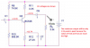
Design a circuit using BC546 that gives us the gain of 1500
R(in)=2.5KΩ
R(out)=3.3KΩ
R(source)=50Ω
R(load)=3.3KΩ
Vcc=15 volt
and assume ro=infinite

the problem is I don't actually know how to start solving it if you can help me I would be very grateful.

in addition I have questions before starting :
1- How many stages should I use?
2- is common emitter configuration proper for all of the stages? and what is the reason?
 
Last edited:
the problem is I don't actually know how to start solving it
Were you paying attention in class :)?
Revise what you have been taught. Start by considering which transistor configurations give reasonable gain and what their input and output impedances are likely to be. Post your best effort at a solution.
 
Were you paying attention in class :)?
Revise what you have been taught. Start by considering which transistor configurations give reasonable gain and what their input and output impedance are likely to be. Post your best effort at a solution.

thanks
I did it mostly by using 2 stage winch both have common emitter configuration but I'm still stuck with R(out)=3.3KΩ
in the second stage below you can see if I want R(out)=3.3KΩ while RL is already equal to 3.3KΩ then R6 will be so great that almost no current will flow through the collector. meanwhile I need a cuurent between 1 to 10 mA for collector to get to a suitable beta according to datasheets and if it goes around μA or less then I would have no idea about the amount of beta
can you help me with this last problem?
el.PNG
 
RL is not part of the amplifier, it is the load.

Looking in to the amplifier, you will see R6 and the transistor are effectively in parallel. The output impedance of Q2 will be very high so you are left with R6 as the output resistance, assuming C1 has a low impedance at the frequency of interest.
 
RL is not part of the amplifier, it is the load.

Looking in to the amplifier, you will see R6 and the transistor are effectively in parallel. The output impedance of Q2 will be very high so you are left with R6 as the output resistance, assuming C1 has a low impedance at the frequency of interest.

thank you very much
as the last question::)
How can I determine the amount of resistor on the collector the stage before the last one?
in fact I have all the parameters of the last stage
but I to determine R7 and R8 I can't
because I have 4 unknown parameter about the transistor "Q2":
R7 , R8 , Ic , Vce
and there is only 3 equations:
AC load line equation , DC load line equation , Gain equation
so what am I missing here? what should I do?photo_2017-11-11_18-02-45.jpg
 
Your assignment says that "ro is infinite". Isn't ro your RL? Then remove your RL.

I think you must learn about transistors because your resistor values appear to be selected at random.
Here is the operation of your second transistor:
 

Attachments

  • transistor.png
    transistor.png
    220.7 KB · Views: 154
Top