Maker Pro
Maker Pro

delay on timer

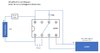
I’m trying to build a small circuit with a delay timer which turns a component on after a short delay. I made one using a 555 timer chip based on instructions seen in the video at this link: How to make 3 volt timer circuit, delay timer diy circuit - YouTube. When I hook up an LED to test the circuit, it works exactly as I expect, turning on around 2 seconds after I flip the power switch. However, when I replace the LED with a laser pointer, it no longer works; in fact, it seems to render the laser inoperable (even when connected directly to a power supply afterwards). I have included a schematic which shows the components I used, and how I wired them to the 555 IC. Can anyone tell me why this isn’t working, and also what I would need to do (or add) to make this work? Please keep in mind that I want the smallest footprint possible for this delay circuit; the enclosure I’m trying to fit this in is very tight, so any solutions which take up too much space may not be viable.
 

Attachments

  • timer circuit diagram.jpg
    timer circuit diagram.jpg
    46.9 KB · Views: 17
The NE555, and the LM555, which is National's copy of the NE555, are rated for operating voltages between 4.5 V and 16 V. Source: datasheet

ak
 
It is not a delay off timer circuit. When I attach an LED bulb to it, then the light goes on ~2 sec after I flip the switch. It does not work when I replace the LED bulb with a laser pointer.

Depending on the colour of your Laser LED, kit may require up to 4V to operate.
See link.

Light Emitting Diode or the LED Tutorial (electronics-tutorials.ws)
A new model of this laser pointer runs fine with a 3.3V input when connected directly to a power supply. After trying to run it with my timer circuit, then the laser stops working.

The NE555, and the LM555, which is National's copy of the NE555, are rated for operating voltages between 4.5 V and 16 V. Source: datasheet

ak
Thank you for that info, but why does my circuit work with an LED bulb but not a laser pointer?
 
Thank you for that info, but why does my circuit work with an LED bulb but not a laser pointer?
Probably because the LED draws less current than the laser. Note that the laser overloads the 555 output stage. If you want a better answer, consider providing enough information to form one.

LED make
LED part number
LED voltage
LED current
LED current limiting

ak
 
Probably because the LED draws less current than the laser. Note that the laser overloads the 555 output stage. If you want a better answer, consider providing enough information to form one.

LED make
LED part number
LED voltage
LED current
LED current limiting

ak
Thank you for the reply. I was not really sure what additional information was necessary because my electronics knowledge is not very extensive, but your answer makes sense. The LED voltage is 3.2V and its current is 30mA. Here is a link to the LED if that helps: https://www.digikey.com/en/products...098?s=N4IgTCBcDaIMwFYAMBaMBOA7AFhQOwBMQBdAXyA.
However, the question now becomes, is there a component I can add (possibly between the 555 timer and the laser), which will make this circuit work correctly? And if so, how would I do this?
 
Based on the part number, your LED has no internal current limiting. If actually true, the only reason it hasn't failed is that the battery voltage is so low.

You can increase the circuit's output current capability by adding a small, n-channel, power MOSFET between the 555 output and the laser. I think the circuit still will behave erratically because of the low power supply voltage. The chip you have has enough operating margin to perform at 3.3 V, but it is entirely possible (probable?) that the next chip won't work.

ak
 
I think the vast majority of 555's can output about 200mA max, some will be less. I see that your device demands just over 300mA. If that is so, you 555 output stage may be going into current limit or simply saturating. This will cause the output voltage to collapse which would explain why your device will not work. As suggested elsewhere another transistor on the output may resolve this. A Mosfet may not be the best choice as many will only be partially switched on with the volts available.
 

bertus

Moderator
Hello,

The bipolair NE555 will work between 5 and 15 Volts:
NE555_features.png
The CMOS LMC555 will work between 2 and 15 Volts:
LMC555_features.png

Bertus
 
I think the vast majority of 555's can output about 200mA max,
Only bipolar 555's; and, again, not when running on 3.3 V. CMOS versions are rated to run on 3.3 V, but can deliver only 10/50 mA. See bertus's partial datasheets above.
As suggested elsewhere another transistor on the output may resolve this. A Mosfet may not be the best choice as many will only be partially switched on with the volts available.
I want to update my previous response, but am locked out. It would take a *p-channel* MOSFET with a low threshold voltage, but there are many to choose from. I mentioned a MOSFET because it doesn't require a base current limiting resistor. A PNP bipolar transistor also will work. Either way, you still need a CMOS 555 to run on such a low voltage.

ak
 
Last edited:
Perhaps try something like either of these NTD25P03L, STD25P03L. They are logic level Pmosfets with low on resistance.
 
Top