Hi! New guy here!
I'm designing a DC power supply. Here are the specifics:
1. 230Vrms 60Hz AC source
2. 5V, +/-15V, 1.2V to at least 20V variable outputs, all grounded, 3A max current overall
3. resettable short circuit protection using relays
4. pass transistor to increase current output of voltage regulators to the required max current
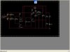
I need some tips on how to design the short circuit protection as well as the pass transistor. I've attached a screenshot of my schematic. I'm still unsure of the transistor, resistor, and relay specifications so I think there's no reason for me to include them.
By the way, I'm also having trouble with the step-down transformer. How do I make it deliver 3A max current to the whole circuit without problems?
Thanks in advance.
I'm designing a DC power supply. Here are the specifics:
1. 230Vrms 60Hz AC source
2. 5V, +/-15V, 1.2V to at least 20V variable outputs, all grounded, 3A max current overall
3. resettable short circuit protection using relays
4. pass transistor to increase current output of voltage regulators to the required max current
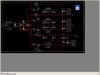
I need some tips on how to design the short circuit protection as well as the pass transistor. I've attached a screenshot of my schematic. I'm still unsure of the transistor, resistor, and relay specifications so I think there's no reason for me to include them.
By the way, I'm also having trouble with the step-down transformer. How do I make it deliver 3A max current to the whole circuit without problems?
Thanks in advance.
")