Maker Pro
Maker Pro

Custom Clock

I want to build my own custom clock. To save space I need to know if there is a single microprocessor that can do this.

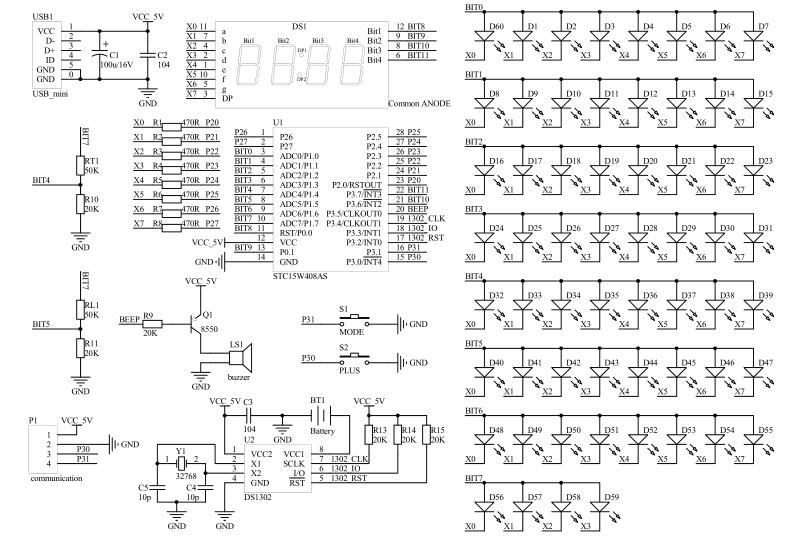
It must control the 4 digit 7 segment counter that shows the time. Indicate AM/PM

Plus, I want to use 60 LEDs circling the clock face that will light up one LED for one second, turn off, light up next LED, etc..

I will also need to know the best way to program the microprocessor.
 
Last edited:
What research have you done so far?
There are thousands of different ways and types.
Google is full of ready made and kit versions.
I will also need to know the best way to program the microprocessor
The best way is the correct way.
One example circuit from Google.

1ccf0316-8a30-4109-b79b-1510a1d7c1f7.png

Martin
 
Last edited:
A nice processor to use to do this is the Espressif processor, especially if you have a home Wifi network available. It has enough I/O pins and as a bonus it has Wifi that allows you to retrieve the time from the internet should there be a power failure, meaning you never have to set the time again. You can most likely get away with using an ESP32-S2 although the ESP32 has better support in the Arduino workbench(which is easier to install and use than the ESP software). You can download existing libraries that do all the functionality that you need, excluding the second leds, but they are very easy to implement (see post by Martaine2005 above for a matrix implementation). These processors are about $2-$3 and has builtin flash, ram and realtime clock that should be enough for your project.
 
If you want to go completely outside the box so to speak, a good choice would be Digilent's CMOD A7. It uses an Artix-7 FPGA. There are 44 DIO signals on a simple DIP row package or 48 pins. You can use VHDL or Verilog to program it and if you still want a processor you can instantiate one from xilinx the Microblaze. Being that what you are doing is fairly straight forward digital logic, you can probably just code that up in VHDL or Verilog. For you 60 LED's I would recommend 6 banks with digital output driving high each bank and 10 leds in both banks. By doing this you will save a lot of IO. Only 16 IO pins would be needed for your second hand. Being that all of the logic is inside of one chip, the circuit would be really simple. The device already has on board clocks as well. It is a nice module. Because the module is on 0.1" on center DIP, you can use a simple protoboard and not have to create a PCB unless you wanted to.
If you are not familiar with VHDL/Verilog. You can still use this and just write all your code in C programming language for the micro-blaze. There is a little learning curve being you have to get the micro-blazed attached to the IO pins via ports. But not to difficult.
 
Last edited:
Top