Maker Pro
Maker Pro

Current sensing circuit help

(*steve*)

¡sǝpodᴉʇuɐ ǝɥʇ ɹɐǝɥd
Moderator
It looks looks you ignored most of my advice.

In addition, you're now not using the current transformer correctly.

I'll draw you a circuit... Hang on
 

(*steve*)

¡sǝpodᴉʇuɐ ǝɥʇ ɹɐǝɥd
Moderator
upload_2017-12-28_14-57-31.png

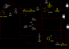
I haven't drawn the mains side.

The current transformer has a resistor across it. Ideally you pick the value of the resistor to have about 0.5V across it at the maximum load. In your case, you can increase the value of the resistor to increase sensitivity. For the highest sensitivity you might even be able to remove it.

The diodes D3 and D4 are CRITICAL to prevent the voltage across the current transformer from exceeding about +/- 0.7V.

R2 and R2 determine the gain of the precision rectifier. It is set to 10 at the moment. You could increase that if you desire.

R5 and R6, C1 and C2, form a voltage divider to give you a split rail.

R3, R7, and R8 allow you to trim the offset of the op-amp.

In operation, you have the load completely disconnected and you adjust R8 for a 0 reading. Adjust it so the reading is just 0, going further will reduce the sensitivity. if you can't zero it, this may be due to variations in resistor values. Using 1% resistors for R3, R7, R5, and R6 will help. swapping resistors around, or carefully choosing resistors for very similar values may be necessary. In the worst case, increase the value of R8, although this will make it harder to zero the meter accurately.

Then connect your load. The meter will only read positive. If you are using a multimeter, auto-range it or reduce to a more sensitive range for lighter loads.
 
upload_2017-12-28_3-26-17.png

I am finding it difficult to zero out the output, the closest I got to zero is 1.8 uV. After I got it to 1.8 uV I tried applying a load to the circuit but I get no change in the output whatsoever. I have tried a 0.1 watt load and I even went as far as to put a 1ohm short just to see if I can get the output to change with no luck. I also attempted to adjust the gain with no luck. Any ideas? Also I just tried that random op amp to see if it would help at all but it did not. the original op amp I had in that circuit was an LM324N but it too did not work.
 
Last edited:

(*steve*)

¡sǝpodᴉʇuɐ ǝɥʇ ɹɐǝɥd
Moderator
1.8uV is plenty close to zero.

You have missed a ground connection (on one side of the current transformer -- near D1 on your diagram).

And I see you worked through the other questions you had :)
 
I just added the ground connection and the simulation is working! the only thing is I need the output to go a little higher at .1 watts, I tried adjusting the gain. I changed R2 to 1Mohm and R1 to 1Kohm. is there anything else I can change the bring the voltage up?
 
Also it occurs to me that when I go to build this circuit I do not know where to hook up my ground points? I have a transformer less power supply with 14 volts. Once I split the rails, my negative rail will be at -7 volts so I can not reference to that, I need to reference to zero volts. Should I use my neutral connection on the mains side of my rectifier as my ground? Will this cause any issues? Also just so you know my plug is polarized so it can only go in one way so I have no fear of accidentally flipping the mains and blowing up my circuit :)
 

(*steve*)

¡sǝpodᴉʇuɐ ǝɥʇ ɹɐǝɥd
Moderator
With a transformerless power supply (which I interpret as using a capacitor) you should connect NOTHING to mains earth.

The earth connection you have in your simulation is probably required to make the simulation work.

With this type of power supply you need to treat the correct as if each and every part of it is at mains potential. This includes the output to your multimeter. An internal meter would be much better.

Show us how you intend to get your 14V and I may be able to say more. You do realise that there are some very small mains transformers available too?

Given the changes you've made to R1 and R2, there's not a lot more you can do (other than a current transformer with a lower turns ratio).

I'm not sure at the moment if your"testing" has been real (practical) or simulated (theoretical). As you should know, in theory there is no difference between theory and practice, but in practice there is.

Without the R4 that you have removed, the output level will be determined by the input impedance of your amplifier (which you have sent to a low value (1k)). I would recommend you try adding a voltage follower between D2 and R1, and then look at the operation. You will probably need to reduce the sensitivity then (by adding a high value R4). I suspect that you'll also be able to reduce the gain of the precision rectifier too.
 
upload_2017-12-29_2-47-37.png

This is the power supply I am using. The ground connection is only there to make the simulation happy. I changed the specs of D2 to be a 14V zener diode. I just checked with a volt meter and if I reference to ground I get roughly +7 volts and roughly -7 volts... my total between both sides of D2 is 13.969VDC. Am I wrong in saying that I will not be needing that circuit to split the rails considering that my power supply is already splitting the rails.
 

(*steve*)

¡sǝpodᴉʇuɐ ǝɥʇ ɹɐǝɥd
Moderator
I would not recommend it.

It would be better to replace the single 14V zener with two zeners of approximately half the voltage and place a 10uF capacitor across each.

Also ensure that your capacitor C1 is rated to be placed across the mains. If it fails, everything in your circuit is likely to go bang.
 
I tried to find a small 14 volt mains transformer but I could not find one that was small enough for my application which is why I chose the transformer less route.
 
I will post an updated schematic for the power supply. Also for C1 I chose a capacitor which is good up to 240VAC and when/if it fails it fails open.
 
Why is using two zener diodes safer then using one? Is it safer so that in the event that my zener diode blows open I will at least having another one to clamp the voltage down? If this is the case cant I just use 1 14v zener thats rated for lets say 5W and then throw a 1 or 2 amp fuse in to the mix in case of over current due to component failure?
 
upload_2017-12-29_4-7-7.png

I replaced the battery and the rail splitting circuit with my power supply however I now can no longer zero out the output of my op amp. I do not understand why this isn't working. I checked with a volt meter, I am getting +6.995V and -6.973V and I am hooking up the power the same way it was before but the circuit is not functioning the same way. I intend on replacing the zener diode on my power supply with 2 zener diodes and 2 10uf caps like you suggested I just wanted to see if it would work this way.
 

Attachments

  • upload_2017-12-29_4-6-35.png
    upload_2017-12-29_4-6-35.png
    55.5 KB · Views: 113

(*steve*)

¡sǝpodᴉʇuɐ ǝɥʇ ɹɐǝɥd
Moderator
The point between the two zeners is your middle rail. DO NOT connect it to the mains as you have done.
 

(*steve*)

¡sǝpodᴉʇuɐ ǝɥʇ ɹɐǝɥd
Moderator
Well, do you remember that you were originally taking the voltage from both ends of a zener?

Now you have two zeners together that give the same voltage, bit now with a mid-rail generated between them.
 
Ok I understand that but you said that I hooked up the mains to the middle of the two zener diodes but I hooked up the zener diodes to the DC side of my rectifier? So my question is what did I do wrong in this circuit.
upload_2017-12-29_3-31-42-png.38169
 
Top