.
Sir East Coast Toast . . . . . . .
My . . . My . . . My . . . . . I am surprised in your not coming up with a minor rotor adjusting in getting that CTS pot fully functional again.
Let me give you some more precise details.
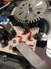
Note that I am using the solder ring terminals vs your pcb solder stakes, but the ROTOR spring tensioned contacts are being our point of interest.
After loosening the four bend over tabs on the pots periphery, it should come apart.
Bourns , Stackpole, Allen Bradley and others make it harder by having a captive circular 1 turn ring around the pots shaft, where I show my
GREEN ring. Some rings are circular and rest down within a groove around the shaft, others have a square cut within the shaft and use a
square cut circular ring to compress down within the shafts groove. In either case, their purpose is to hold the shaft captive within the outer
threaded control collar, used for mounting the pot to a panel.
In those latter cases, one needs to hold half of the shaft with a pair of properly tensioned vise grips and then a jewelers screwdriver gets down
within the split in the ring and uses the adjacent solid vise grip jaw to lever against to start the ring spreading and coming out of the groove.
Once initially loosened, two levered jewelers screwdrivers will then spread the ring enough to slide it up and off the shaft.
The rings re-installation is just its placement into the groove and use of the vise grips for compressing it into the groove.
BUT . . . I think that your particular CTS series being utilized, just comes apart, with no retainer ring involved.
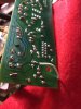
Examining the pots photo, the tensioned phospor bronze contact assembly has a dimple back at B that presses against rotary contact ring B'
At the front there are two spaced apart A contacts involved that ride around the resistance element ring at a contintally shifting point B'
You should reassemble the shaft into the collar and only leave the outer switch cover off, so that eyeball observation is possible.
With the unit now compressed with your clamping fingers , a bright light inspection should reveal the loss of contact of B or A.
OR keep an ohmmeter clipped across center rotor to one and then the other side tab contacts, to see if an open developed within a full 270
degree rotation.
If corrective tensioning of B is needed, a flat jewelers screwdriver tip under both of the REAR 2 RED DOTS positions can be used to lift
the dimple up approx 1/16 inch.
Use the same procedure on the pair of front A contacts at the FRONT 4 RED DOTS to initially lift up one contact 1/16 in as reference against
its companion contact , then adjust the other contact to be level with the prior adjusted ones position.
When reassembled, I can't see that unit then not functioning flawlessly.
UNLESS . . . its real problem is where I have it marked up with the YELLOW STARS.
The very low resistance element extreme ends are compressed into contact with the end terminals at the GREEN C areas.
To test a possibility of a loose compression crimp, ohm from the Star areas on a resistance element end to inside its ring contact YELLOW DOT.
Wiggle the contact to see if an open connection occurs.
If finding that the case, to avoid a touchy terminal crunching /bakelite cracking situation, I close up a pair of vise grips, yet such that the jaws are
still being approx 1/4 inch opened.
Then the jaws are placed on the top and bottom of the pots compressed connection and the adjustment screw of the vise grips is tightened , just
like you had a micrometer in hand and was adjusting it in to mike the compression terminals thickness.
When its snug, open the vise grip jaws and place a small piece of sheet metal (***) between the top jaw and the compression terminal.
Then, you fully clamp down on the vise grip handles, and you have produced a precisely controlled, non destructive compression.
(***) My small piece of sheet metal is being the thickness of a playing card and was a part of a strap stand off from my old TV antenna . . . taken
down decades ago.
Soooooooooooo, just in case you haven't been that precise in your pots evaluation, take this Edd-u-cation in hand, and see if it is applicable to
your pots situation.
Otherwise, locating another JUST LIKE Pot/Sw, might be vewy-vewy hard, and a year(s) long search of new or used old stock.
73's de Edd
.