Maker Pro
Maker Pro

converting constant-current PWM from a TLC5940 to voltage

hi everyone,

this is my first post here, so please forgive me if i've posted in the wrong place.

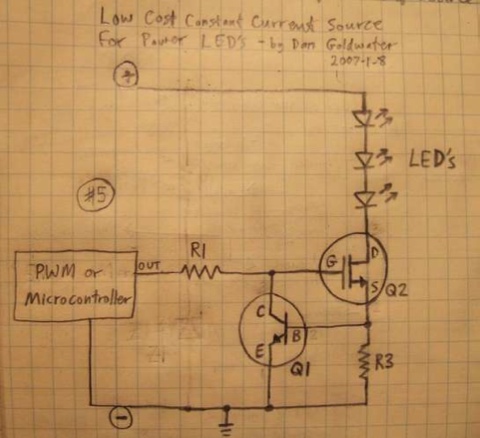
i'm developing a circuit that will use many LEDs, mixing ordinary 5mm leds with 350mA Luxeon Stars. i am using this circuit on Instructables (Circuit #5:
luxeon_driver.jpg
) to provide power for the LED, using a separate power input.

to control PWM, i'm using a Texas Instruments TLC5940 LED driver. this allows an adjustable maximum constant current to flow through leds connected at each of the output pins. i have the maximum current set at the moment to 1mA, and it works fine for standard 5mm leds of any voltage: the cathode of the LED goes to the OUTn pin of the TLC5940, and the anode goes to the +5V supply.

but, to control my Luxeons the driver circuit needs an input voltage sufficient to trigger the MOSFET (an IRFZ34E), and i'm having difficulty figuring out how make this work. i initially assumed i could put a resistor in place of one of the ordinary 5mm LEDs, with resistance R = V/I = 5V/1mA = 5kΩ and then put the ground and control voltage input from Luxeon driver across this LED, with the ground to the TLC5940 side of the resistor and the control input on the +5V side.

plugging in just the resistor and measuring the voltage across it gave reasonable enough readings across it (around 4.2V). but when i connected up the LED driver it didn't at all do what i was expecting: putting the ground from the external supply in particular seemed to kill the TLC5940, which i had to then power-cycle to get running again.

i'm in over my head here. could somebody give me some clues about what's going on, and what i might do instead of what i'm currently doing, which is clearly not the right thing to do :)

cheers!
d
 

(*steve*)

¡sǝpodᴉʇuɐ ǝɥʇ ɹɐǝɥd
Moderator
This circuit works as follows:

R3 is calculated to drop 0.7 volts at the maximum allowable current for the LEDs. If this is 1A, then the resistance is 0.7 ohms.

Q2 is a mosfet which turns on when the gate becomes several (5 or more maybe) volts higher than the source.

R1 limits the current that can be supplied by the PWM circuit.

The PWM circuit supplies a variable mark/space ratio square wave of at least 5 volts amplitude.

Without considering Q1, the circuit operates as follows:

The PWM controller turns Q2 on and off for a variable amount of time. with a higher mark/space ratio the transistor is on more than it is off and the LEDs are on more than off, so they are bright. With a lower mark/space ratio, Q2 is off more than it is on and so the LEDs are dimmer.

However, without Q1 the current through the LEDs is not limited. They will burn out very quickly.

Q1 is arranged so that when the voltage across R3 reaches a point at which it (Q1) begins to turn on, it steals current from the gate of Q2. This current comes from the PWM signal, and R1 then drops some voltage so the voltage on the gate of Q2 drops. As the gate voltage is reduced, Q2 allows less current to pass. The effect is that the current passing through the LEDs is limited to the amount which causes 0.7volts (or thereabouts) to be dropped across R3.

Depending on the current and the supply voltage, Q2 may get quite warm and require a heatsink.

I would recommend using something other than a TLC5940 to generate the PWM signal. That's just not something its designed to do. (or are you trying to get this to control much larger LEDs?)

I'm not sure what your problem was in using the TLC5940 the way I think you mean. 4.2V is very much on the low side for the gate voltage. You may be able to get away with it for some mosfets. For this one, it is specified for a Vgs of 4.5V but you're very clearly in marginal territory. you should be aiming for 10V at least. You could try replacing the mosfet with a "logic level" device.

As to why your IC got upset, I can't answer that without clearer information. You should be able to use a common 0V line (indeed you would need to). I assume you're using a VCC of around 6V for the TLC5940?
 
Last edited:
Are you trying to run the Luxeons at 1mA? If memory serves, I don't believe they start to light until 5-10mA, and even then you'll just start to see the die glow. They don't start to get "bright" until 30-50mA or so? Keep in mind they're 'supposed' to be run at 300mA, with a max of 350mA. Though for that, you WILL need a good heat sink, above and beyond any "star" PCB they may be mounted to when you got them.

It's been a while since I've used the Luxeon though, more versed on the Rebel, which I do know don't start to produce any light until about 5mA, with an applied Vf in the range of 2-2.5V.
 

(*steve*)

¡sǝpodᴉʇuɐ ǝɥʇ ɹɐǝɥd
Moderator
On your web site, I think you bay have V1 and V2 reversed.

A V1 of 5V will not provide sufficient drive for the gate of the mosfet., and a V2 above 5V (or thereabouts) will result in potentially high dissipation in your mosfet.

Did you get them around the wrong way?

Also R1 and R2 are quite high and may result in quite slow switching. This may not matter unless the LEDs are switched rapidly (say for PWM brightness control)
 
hi again steve, + thanks for your continuing assistance!

V1 does provide enough voltage, i selected Q2 to ensure it had a fairly low switch-on voltage (according to the datasheet the 'on' voltage for this mosfet is 2-4V). i want V2 to be quite high (+12V) because in some cases i need to run 3 4V LED's in series. i'm aware of the heat dissipation this will cause on Q2.

thanks for the R1-R2 tip. it seems to work in practise with PWM switching but i might try changing them and see what happens.
 

(*steve*)

¡sǝpodᴉʇuɐ ǝɥʇ ɹɐǝɥd
Moderator
Mosfets have a significant spread of characteristics -- far more than bipolar transistors. Maybe your circuit is OK for that mosfet, or maybe you got lucky and have some with a low turn on gate voltage.

If you look a the graph of Id vs Vds for various gate voltages you'll see that your max Id for Vgs below 5V plummets. It is likely to be well below 1A at 4V. In your circuit, the max gate voltage is 5V - Vce(sat) for the transistor.

Fortunately Vce(sat) is very low in the transistor you've chosen (it surprised me). It looks like you should get 4.5V at the gate.

The other issue is the turn on and turn off time of the mosfet. You are allowing a max of 50uA of base current to turn it on, and 25uA to turn it off. The base charge is 30nC. This means it takes 1.5ms to turn the mosfet on, and 3ms to turn it off. (I predict 55p may pop up and give you even worse figures because the gate current is not constant)

If the LED is being driven using a PWM technique to change brightness, it is likely that your technique will just cause some indeterminate constant current to flow due to the mosfet being neither on nor off.

In your case it's probably not a huge issue as the mosfet is going to be dissipating the same energy, however the average current may not vary exactly the same way it does for the diode being mirrored.

Reducing the resistors to (say) 1k would improve turn on/off times a factor of 100.
 
When you copy stuff from the internet without actually understanding it, you do not know the type of crap you are going to get. This "current mirror" implementation is crap. If you go back and read the comments on the website that he references as the source (the thread on eng-tips) they tell him that what he is doing is wrong, but he boldly keeps on doing the wrong thing and giving them credit.

The TLC5940's output is an analog current sink. You can set the current to whatever value up to about 60mA. That sets the on current. You can then PWM the output to achieve the further dimming.

If you truly want your high current LED to work with both the current setting and PWM features, you need to implement a real multiplying current mirror (originally recommended in the eng-tips thread), where the output leg is a multiple of the input leg. In that setup, the transistor Q3 is the output drive transistor and the LED goes where R2 is. R1, R3, Q1 and Q2 are not needed. You will need to upgrade Q3 with something really beefy so it can handle the power for driving the LED.

You can improve that circuit a bit by doing a transistor/MOSFET hybrid current mirror design, that uses a MOSFET as the actual load driver, while the transistors set the current.

This circuit, as drawn, is pure rubbish. It is not a current mirror, not at 5V, not even at 50V. For the current mirror to function as a current mirror, the load (R2 in this circuit) has to be relatively low resistance. With a 100K load, as soon as any current flows, the voltage across R2 is going to go right up to the voltage at Q4's collector and stay there.

All this circuit is doing is turning on Q2 as soon as TLC5940 turns on and and doing that really badly for the reasons Steve pointed out (R1 is too big). And that only happens if the set current is less than about 10mA, At 10mA, the collector voltage of Q3 is about 2V, far too little to turn on a MOSFET that turns on at 2V (the 2-4V turn on means that it MAY turn on at 2V, it is not GUARANTEED to turn on till 4V).

If all you want to do is PWM, then you need a simple P channel MOSFET that is driven by the output of the TLC5490.

---55p
 
Last edited:
hi steve,

i guess, it seems i got lucky -- measuring the current passing through the MOSFET it sits at around 350mA when PWM is always on, and the light smoothly (logarithmically) dims as the PWM pulse width decreases to 0. thanks for your comments, they were enlightening. i hadn't realised that timing would be an issue in this case.

hi 55pilot,

thanks for your comments. i'm not an electronics engineer and i don't pretend to be. i'm just trying to get something that works for me in the context of the construction of an art project. i understand that it's not a proper 'current mirror' and that the voltage across R2 immediately goes to the Q4 collector voltage. that's what i thought i wanted, and that's why i chose such a high value. all i'm interested in 'mirroring' is actually the PWM part of the signal. i've taken on board steve's comments about 100k being too high. i wasn't aware the timing would become an issue, i was more interested in getting that high enough voltage to turn on the MOSFET.

i attempted to construct a multiplying current mirror, spending several days reading widely about current mirror designs and experimenting both with John Falstad's circuit simulator and with proper components, but i just couldn't get anything to work reliably with the 35-70x high-current gain i required (10mA : 350mA or 700mA, depending on the LED used).

please could you help me to understand your suggestion, because i'm likely to make another mistake if i try myself without understanding.

If you truly want your high current LED to work with both the current setting and PWM features, you need to implement a real multiplying current mirror (originally recommended in the eng-tips thread), where the output leg is a multiple of the input leg. In that setup, the transistor Q3 is the output drive transistor and the LED goes where R2 is. R1, R3, Q1 and Q2 are not needed. You will need to upgrade Q3 with something really beefy so it can handle the power for driving the LED.

forgive me, but there is very little information online about how to design a multiplying current mirror. what does the basic circuit look like? how do i set the multiplying factor (to x35 or x70, making a 350mA or 700mA output current from a 10mA input current)?

If all you want to do is PWM, then you need a simple P-channel MOSFET that is driven by the output of the TLC5490.

in this case, how would i ensure that the current passing through the LED is limited to 350mA (or 700mA)? ideally also, in a single design that can deliver constant current over a variable input voltage between 5V and 12V (which, if i understand correctly, is what the Q1/R3 arrangement in the 'crap' circuit that i am currently using is doing).

thanks in advance for any help,
damian
 
Last edited:
In the circuit you have posted above, Q1 and R3 indeed limit the current flowing through the LEDs. If the PWM output were a voltage between 0 and 5V or even 0 and 3V the circuit would work with an appropriately sized resistor (a few hundred ohms to a few K ohm). For 350mA, R3 will need to be 1.8 ohm, or six 10 ohm resistors in parallel will get you 385mA or five 10 ohm in parallel will give you 325mA. The 1.8 ohm needs to be rated for 1/2W or larger. The 10 ohm can be 1/4W or even 1/8W. Your biggest problem is going to be power drop in Q2.

If you wanted to just take the PWM out of a TLC5490, what you need to do is to connect a resistor from the output to the base of a PNP (2n3906 is one choice) and another from the base to the emitter of the PNP, which is connected to 5V. The collector of the PNP connects to the left side of R1 (left in your schematic above). The two resistors connected to the base of the PNP can be 1K if you are sure that the current on the TLC5490 will be 5mA or larger. If for some reason you need to set the current less than 5mA, then you need to make the resistors larger. You can set the current higher without limit, as the 1K will not allow more than 4.5mA to flow.

Doing the current mirror is quite simple in theory, but a bit more involved in practice. The output transistor will be dropping a lot of power. At 350mA, the output transistor will also have a lot of gate current that needs to be accounted for. You are almost forced to consider a transistor/MOSFET hybrid current mirror, which is a bit more involved to design and get to work reliably. You still need to worry about the power drop in the output MOSFET.

The big question is, do you really need one?

---55p
 
hi again,

@55pilot thanks for the help. everything's working great now, following the instructions you posted.

cheers again
d
 
Top