Maker Pro
Maker Pro

controlling amplitude of LED osc

So I tried this circuit in my breadboard and managed to get it to work correctly for the most part. One question that has stumped me is how to control the amplitude margin.
16076554-7352-4680-a32f-dbe525574890.jpg

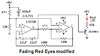
This is the circuit in principle, though I am just using a single LED and 12 volts rather than 5. Also I am using a 2N3904 bipolar transistor rather than the mystery transistor listed.

I can get the LED to brighten and dim considerably with a 1.5k ohm resistor in series between the collector of the transistor and the LED. If I step it up any higher than that, say 2.2k or 4.7k, it seems to only get dimmer and not much brighter. A 470 ohm resistor causes it to stay bright with a barely noticeable difference in change during cycles.
 

davenn

Moderator
So I tried this circuit in my breadboard and managed to get it to work correctly for the most part.


HI there
welcome to EP :)

I have moved your post to its own thread. Although it is on the same topic as in the other thread, your post wasn't helping the other poster with
a solution etc. You were asking a totally different Q on a similar circuit :)

cheers
Dave
 
1) Your 47uF capacitor tries to be driven with backwards polarity half the time. Connect two 100uF capacitors back-to-back.
2) The LM358 output voltage does not go high enough and the NPN emitter-follower makes it worse. Use a PNP emitter-follower instead. Mine has different battery voltage, resistor values and capacitor values:
 

Attachments

  • fading LED eyes modified.PNG
    fading LED eyes modified.PNG
    6.7 KB · Views: 8

(*steve*)

¡sǝpodᴉʇuɐ ǝɥʇ ɹɐǝɥd
Moderator
@Audioguru I think the use of an emitter follower may be a feature rather than a bug.

@ke4cpc Rather than use two capacitors, you could replace C1 with a 1uF nonpolarised cap, and change R4 to something like 1M.

The maximum brightness will be affected by the supply voltage. As pointed out, you're operating the LM358 at a very low voltage, and increasing that may allow you to achieve a better result. Unless your LEDs are high power devices, it may be best to increase the value of R6 and R7 while you're resting things.

Changing the ratio of R1 to R2 should impact the maximum and minimum brightness (I think).

Since you have this on a breadboard, go ahead and experiment with some of these things and see how it goes.
 
@Audioguru I think the use of an emitter follower may be a feature rather than a bug.
Of course you need to use an emitter-follower but since the output of the LM358 does not go to a high enough voltage then you need to use a PNP emitter follower like I showed.

@ke4cpc Rather than use two capacitors, you could replace C1 with a 1uF nonpolarised cap, and change R4 to something like 1M.


I do not think a lousy old LM358 can work with a 1M resistor.
 
Last edited by a moderator:
Top