I need to post a revised edition of the schematic. You will need 2 sets of batteries, the transmitter runs off 3-12 Volts and the PIR sensor runs off 5-25 Volts, needing only 1 battery for the outdoors module. However the receiver module runs off 3.3-6 Volts whereas your light runs off 12 Volts, this means for the indoors module either an extra set of batteries id required or you will need to use a voltage divider, the revised edition I have provided uses the voltage divider method. Both of the batteries shown are 12 Volts, the battery in the indoors module will need to be this voltage, the outdoors battery can be any voltage from 5 to 12 Volts, I would suggest something towards the top end of this range to give the receiver the best possible power.

The schematic shows:
Outdoors module:
1. The battery is connected to the positive supply (Vdd) of the PIR sensor and the RF transmitter, ensure the battery is connected in parallel with the PIR sensor and RF transmitter, to see a basic parallel circuit see:
here. The battery is connected to the ground pin of the PIR sensor and the RF transmitter. The ground symbol can be a downwards triangle or the ground symbol as shown in the resource. (I suggest you read through the above resource if you do not know about Ohm's law)
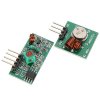
2. The 2 triangles at the top symbolise inputs and outputs, not in this case ground. The output from the PIR sensor is fed directly to the RF transmitter, if you have devices in your house broadcasting on 433 Mhz and 315 Mhz you will need to use something to encode the signal to the transmitter, then decode the signal from the receiver, so you will need to wait wait as I am currently researching into this. But build it first, it should be fine.
Indoors module:
1. The battery is connected to the supply voltage of the receiver through a voltage divider, voltage dividers do what their name suggests, divide the voltage, the voltage divider shown here is halving (roughly) the voltage to the receiver, you can change the values of R2 and R3 so long as they are kept equal, however ensure the wattage does not exceed the maximum wattage rating.
2. The resistor labelled R1 should not actually be 470 ohms, you will need to find this yourself, the value needed for 12 Volts should be shown on the packet, otherwise look up the datasheet.
3. A bipolar NPN transistor (Q1) is being used to turn the load (the light in this case) on and off, the output from the receiver is being fed in to the base (the middle "leg" of the transistor), when the output from the receiver is high the transistor will become saturated allowing all the current to flow, when the output from the receiver is low the transistor will be off allowing none (or rather extremely little, but this is unnoticeable) of the current to flow.
This circuit should work. If it does not post so. I hope this helps you, sorry for the delay.