Maker Pro
Maker Pro

Compaq 5017m 15" LCD Monitor Repair

When first turned on, you can see the Windows desktop, but this computer monitor has "static" or distortion overlaid on the whole screen.

As it warms up, the static gradually decreases. After about 10 minutes, it's mostly gone. After hours, it looks pretty good, but there are still some flickering pixels. The problem cycle is always the same.

I tried connecting it to different computers (video cards), swapping VGA cable (it's 15-pin VGA only), and even tried a different 12v AC-DC adapter. Problem exists, so problem is definitely in the monitor itself.

I just noticed that the On Screen Programming menus seem to be free of distortion, but I'm not sure if that is because the colors are simple/pure or because it's not using the VGA input circuit.

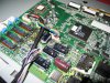
I was wondering if anyone has ever seen a LCD exhibit this kind of problem? Boards look clean and the caps visually look ok.
 

davenn

Moderator
with the OSD looking good, it then indicates a possible VGA processing cctry or
maybe a VGA socket fault on the monitor

what happens if you wriggle the vga lead at the monitor end ??

would be the first time I have seen socket pins on the monitor dry jointing and starting to fail wriggling the cable may confirm that :)

cheers
Dave
 
No, flexing the VGA socket doesn't help. Seems solid and 15-pins soldering to the board looks good.

Yes, I was thinking the same thing about the VGA input processing circuit. The only component I can think of that would "get better" over time is a e-cap. There are only a few in that circuit and they all look fine visually. Those e-caps are the SMT low ones with the fully metal case.
 
Yes, it certainly sounds like bad electrolytics. The bad one(s) could even be on the PSU board. I guess freeze-spray would be the best & easiest way of troubleshooting.
 
would be the first time I have seen socket pins on the monitor dry jointing and starting to fail wriggling the cable may confirm that :)

I went ahead and resoldered the VGA connector "just in case" but the problem still exists.
 
Yes, it certainly sounds like bad electrolytics. The bad one(s) could even be on the PSU board. I guess freeze-spray would be the best & easiest way of troubleshooting.

Yes, there are 2 boards ...
1. PSU (and inverter circuit?) ... backlight plugs in here also.
2. Mainboard with logic, ROM, and video processor. VGA and panel matrix plug in here.

So, even though the OSD works good, you are saying the problem could still be on the PSU board?
 

(*steve*)

¡sǝpodᴉʇuɐ ǝɥʇ ɹɐǝɥd
Moderator
So, even though the OSD works good, you are saying the problem could still be on the PSU board?

Yes, the extra ripple could be affecting the part of the circuit that syncs with the incoming signal. The OSD required no such syncing. So the fault could affect the normal display and not the OSD and be in the PSU as Resqueline suggested.
 
Yes, the extra ripple could be affecting the part of the circuit that syncs with the incoming signal. The OSD required no such syncing. So the fault could affect the normal display and not the OSD and be in the PSU as Resqueline suggested.

So this ripple in the voltage coming from PSU wouldn't really show up on a DVM would it? Maybe just a minor change in voltage? I'm guessing I would need a scope to view the waveform?

Maybe since the VGA input is actually an analog signal, it's more susceptible to interference?
 

(*steve*)

¡sǝpodᴉʇuɐ ǝɥʇ ɹɐǝɥd
Moderator
maybe, maybe, yes, maybe.

Look at the power supply for any capacitors that have domed silver metal tops, or are leaking brown stuff, or that seem "funny" at the base.

Take a picture of that part of the board showing the symptom clearly and someone can confirm whether those capacitors look dead.
 
My best camera is back now, so here are some pics:

The AC/DC 12vdc power supply plugs to the black connector in the lower right of the lower PSU board. VGA-in is the blue connector on the upper board. The other 2 connectors are audio-in and headphones-out.

All the caps look fine on the top and bottom (and no leakage).

The only one that looks different is the larger SMD 470 toward the middle of the PSU board. While the other smaller SMD ones are completely smooth on top, this one has the viewable "Y or T" pattern. However, it's not bulging in any way (it's completely flat on top). I'm just not that familiar with SMD e-caps (and SMT in general) and how they all look when new.

I was hoping to narrow it down to one board or the other, but as the discussion has progressed, it seems that might not be as easy as I first thought.
 

Attachments

  • c5017_inside.jpg
    c5017_inside.jpg
    146.6 KB · Views: 4,587
  • c5017_boards.jpg
    c5017_boards.jpg
    152.6 KB · Views: 2,762
  • c5017_ps.jpg
    c5017_ps.jpg
    163.9 KB · Views: 1,148
Last edited:
Ok, my ESR meter arrived today ... now on to serious trouble-shooting :)

The ESR meter appears to be working fine for both e-caps in and out of circuit. However, some e-caps are reading way off.

So far, I've only checked them in-circuit. This LCD display hasn't been powered-on in a couple of days. I'm also putting a resistor on the solder points of the e-caps before testing just in case.

On the upper board there are many e-caps with the same markings. I assume those should all read the same? To get me started, please help me verify the uF and voltage of these two:

2a
100
16V

22
16s
1PD

Also, if possible, point me to the online documentation used to decipher the markings so I can classify the others.

EDIT: Am I suppose to just use this? The polymer caps never seem to mark/name the manufacturer ... do they all use the same marking system?
http://nichicon-us.com/english/products/pdf/e-wx.pdf
 
Last edited:

davenn

Moderator
hey mate

how ya going on the problem ? have you tried freezer spray as Resqueline suggested
its excellent for finding heat related faults as seems to be in your case.
once the prob starts getting worse as the unit heats up gentle well aimed sprays on single components will most likely show where the fault/s is/are.
A single bigger spray initially to see what happens and to norrow down the section of the cct causing problems then just on individual components ....
pick on components that would obviously run hot anyway .... diodes, regulator chips, higher wattage resistors see what happens.

ALL GOOD workshops have a can of freezer spray on the bench ;)
fault finding in a can :)

Dave N
 

davenn

Moderator
On the upper board there are many e-caps with the same markings. I assume those should all read the same? To get me started, please help me verify the uF and voltage of these two:

2a
100
16V

22
16s
1PD

EDIT: Am I suppose to just use this? The polymer caps never seem to mark/name the manufacturer ... do they all use the same marking system?
http://nichicon-us.com/english/products/pdf/e-wx.pdf

they are electrolytic caps not polymer :) yup the markings may vary between manufacturers your 2 examples i would read as... 100uF @ 16V and 22uF @ 16V

I wouldnt wast too much time on the caps unless they are looking bulged or are up very close to a hot running component like a regulator chip

read my other latest posting about freezer spray it may save you lots of anguish of un-necessary solder reworking of SMD components

Dave N
 
have you tried freezer spray as Resqueline suggested

No, I ran out and haven't tried it yet.

The ESR meter came in today, so I've been learning to use it. Resqueline said it sounded like it might be a cap so I've been going that route. I can't imagine anything other than a cap being bad. It's almost like a timer is installed.
 
they are electrolytic caps not polymer :) yup the markings may vary between manufacturers your 2 examples i would read as... 100uF @ 16V and 22uF @ 16V

I wouldnt wast too much time on the caps unless they are looking bulged or are up very close to a hot running component like a regulator chip

read my other latest posting about freezer spray it may save you lots of anguish of un-necessary solder reworking of SMD components

Dave N

Thanks. So a number by itself on line #1 or #2 is the uF value. Then you look for a number like 4, 6, 10, 16, 25, 35, 50 (that may have a V or some other letter after it) and that is the voltage? The last unused line is the Lot # . Wow ... what a great system :rolleyes:

So normal hole-through aluminum electrolytics are basically the same as these? These only look different (different package) because they are SMD? In another thread, we were talking about these types of caps and calling them polymer. Maybe I'm getting my chemistries and form factors confused.
 
Last edited:
So, I have been testing the hole-thru e-caps on the power board with this new ESR tester. What I'm finding is that the ESR measurement is fairly accurate in the circuit as compared to out of circuit. It also measures capacitance but they usually have to be removed for that to be accurate.

I started at the power input and working by way in. I have break them loose (glued down) just to read the value or to be able to reach the SMD solder points of others close by.

The meter is working because some read very close to the ESR chart. However, I'm find some that are pretty low. Is too low bad also? Like, it should be 0.2 and I'm getting 0.05 ...
 

(*steve*)

¡sǝpodᴉʇuɐ ǝɥʇ ɹɐǝɥd
Moderator
So, I have been testing the hole-thru e-caps on the power board with this new ESR tester. What I'm finding is that the ESR measurement is fairly accurate in the circuit as compared to out of circuit. It also measures capacitance but they usually have to be removed for that to be accurate.

Yes, ESR can almost always be measured in-circuit. And capacitance almost never.

The capacitors to concentrate on (if indeed the problem is a bad capacitor) initially are the ones in power supply, generally those used for filtering SMPS output and any others with high ripple current.
 

(*steve*)

¡sǝpodᴉʇuɐ ǝɥʇ ɹɐǝɥd
Moderator
The AC/DC 12vdc power supply plugs to the black connector in the lower right of the lower PSU board.

I would be looking at this PSU first. Do you have a suitable replacement to eliminate this as a cause?
 
I would be looking at this PSU first. Do you have a suitable replacement to eliminate this as a cause?

Yes, it was one of the first things I tried swapping. This one works fine on a Viewsonic LCD, and the 12v adapter from the Viewsonic doesn't cure the problem with this Compaq.
 
Right, so I'm starting at the 12v in connector and working my way in toward the middle of the board. That's where the final filtered voltages output from the PSU board and go up to the logic board. The other half of the PSU board appears to be the Inverter voltages.

The first hole-thru electrolytic:
C803
470uF
16v

Reads (in-circuit and out-of-circuit)
ESR: 0.05
Cap: 537

-------------------------

Large SMD electrolytic:
C143
470uF
16v

Reads (in-circuit)
ESR: 0.17
Cap: 490

------------------------

According to the chart, they should both read 0.2 ... 0.17 I would say is pretty close. But 0.05 is only 25% of it's proper ESR value. So, is it "reading bad" ?

We have spoken in other threads about "low esr caps" but when does it become a problem. When it's too far out-of-range a problem? Or, (put another way) is this possibly an indication that this e-cap is not preforming properly and might have other problems when engergized?
 
Top