Maker Pro
Maker Pro

Color Organ Kit - Capacitor Substitution OK?

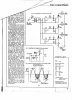
Hi all, thanks for looking at my thread. I bought a 3 channel colour organ kit (designed to coordinate lights to music), and this is the schematic:

[img=http://s29.postimg.org/fuywcli0j/CO_diagram.jpg]

C1 is specified in the parts list as 200u/40v (although it's shown as 220u in the schematic).

The cap I actually received in the kit is marked 330uF / 16v. Can I just go ahead & use the specified cap or should I source the one specified?

Thanks in advance for your help!!!
 

Attachments

  • upload_2014-10-22_19-56-33.png
    upload_2014-10-22_19-56-33.png
    704.4 KB · Views: 318
  • upload_2014-10-22_19-56-57.png
    upload_2014-10-22_19-56-57.png
    704.4 KB · Views: 142

(*steve*)

¡sǝpodᴉʇuɐ ǝɥʇ ɹɐǝɥd
Moderator
Yep, go ahead, you'll be fine. I'd perhaps prefer to see an unpolarised cap in this position, but it will probably survive :)
 
Hi, I'm baaaaack....

OK, so soldering in parts here, and have a couple more questions:

The transformer is a 60-282-0 transformer (center tapped audio transformer?). It has 3 pins on one side, and 2 on the other. My PCB has 4 points to receive it, 2 on each side, evenly spaced. The circuit diagram posted above also seems to indicate 4 connections.

SO - which pin is the odd man out? the center one on one side? And how do I know which side is which? Do I need to pull out a multimeter or something, or does the 3 pin side indicate which one it is?

Also hoping that my small gauge stranded wire (not sure on exact gauge but it's about the same diameter as the resistor / cap leads etc) is going to be sufficient to connect the ac outputs? The pcb won't allow for anything much bigger as currently drilled.... seems pretty small, although I guess they won't be pulling more than 1/2A or so ...

Also I tried determining the polarity of my SCRs with an ohm meter as described here: http://www.allaboutcircuits.com/vol_3/chpt_7/5.html . I'm getting the slightest hit of current in one test probe configuration, before it reverts to the pre-test reading. All the the other probe configurations show nothing, so I guess that one's figured out. Still, if there's a better way to determine the C / A / S leads from the SCR I'd love to hear it.

Thanks again for helping out a poor newB, it's much appreciated:)
 

(*steve*)

¡sǝpodᴉʇuɐ ǝɥʇ ɹɐǝɥd
Moderator
The side of the transformer with 3 pins is going to be the high impedance side. In your case the input comes to the low impedance (2 pin) side. So yes just ignore that centre pin.

If the transformer won't fit in your board you could mount it upside down on the PCB and run wires between the lines and the PCB. A couple of small blobs of got belt glue or silicone adhesive/sealer will keep the transformer in place without being too permanent.

The write you describe seems fine.

As for the SCR, tell us the part number and the package (and/or show us a photo) and we can Point you in the right direction.
 
Thanks yet again Steve, you've really been a great help!

Here's a pic of the SCRs:

It's really tough to figure out what the numbers on them are ... actually trying to do it again I think I have stumbled across the part number, C106DG. My little surge with the ohm tester seemed to indicate that the pins from left to right, with the silver side up (the back?), would be gate / anode / cathode, and that seems to be consistent with the part number info (assuming silver side is the back).

Anyway, I think I should be good to try to finish this thing, thanks again for all the help Steve!!!! :)
 

(*steve*)

¡sǝpodᴉʇuɐ ǝɥʇ ɹɐǝɥd
Moderator
Yes, the silver side is the back (the writing is always on the front/top).

The datasheet indicated that with the writing up and the leas pointing down, you have Cathode (K), Adode (A), Gate (G) from left to right.

The datasheet is a little confusing because it shows the back side in the image above the pinout.

Remember that you've got mains wiring on this device. Be very careful you don't kill yourself or someone else.
 
Yep, seems to like that SCR configuration ... all done and boxed up and working beautifully:) :


Thanks once again for all your help Steve, greatly, greatly appreciated:)

Now to make a nice thunder/control track, and I should have a good thunder & lightning show ready for Halloween!!!

Thanks again!!!!
 
Top