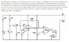
The input voltage to the first opamp never goes positive, then its output also never goes positive. Its input is 0V or is driven negative. All the circuits shown on Google use an inverting opamp that produces a positive output when the input capacitor causes its input to go negative, or biases the (+) input of the first opamp at half the supply voltage so that it is an amplifier.