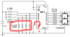
Hi I'm working on a relay clock and I've run into a small problem. I'm trying to read the data sheet for the CD4511 decoders I bought (with my limited understanding of electronics), and am not fully understanding the use of the circled resistors (10k Ohm). I already bought a set of 10kΩ resistors, but knowing their purpose will help me down the road. Many thanks!
-
Categories
-
Platforms
-
Content
")