The one who is engaged in repair of household or industrial radio equipment knows that it is convenient to check the serviceability of capacitors without dismantling them. However, many capacitor capacitance meters do not provide this capability. True, one such construction was described in [2]. It has a small measurement range, a nonlinear scale with a countdown, which reduces accuracy. When designing the same meter, the task of creating a device with a wide range, a linear scale and a direct reading was solved, so that it could be used as a laboratory one. In addition, the device must be diagnostic, i.e., capable of checking and capacitors, shunted with pn junctions of semiconductor devices and resistances of resistors.
The principle of operation of the device is as follows. The input of the differentiator, in which the tested capacitor is used as a differentiator, is supplied with a triangular voltage. In this case, at its output, a meander is obtained with an amplitude proportional to the capacitance of this capacitor. Next, the detector selects the amplitude value of the meander and gives a constant voltage to the measuring head.
The amplitude of the measuring voltage on the probes of the device is about 50 mV, which is not enough to open the pn junctions of semiconductor devices, so they do not exert their shunting effect.
The device has two switches. The “Scale” limit switch with five positions: 10 μF, 1 μF, 0.1 μF, 0.01 μF, 1000 pF. The "Multiplier" switch (X1000, x10O, x10, X1) changes the measurement frequency. Thus, the instrument has eight capacitance measurement ranges from 10,000 microfarads to 1000 pF, which is practically sufficient in most cases.
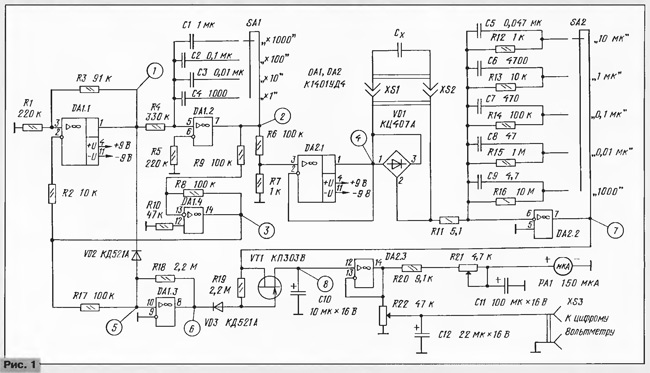
The generator of triangular oscillations is assembled on the OA of the microcircuit DA1.1, DA1.2, DA1.4 (Fig. 1).One of them, DA1.1, operates in the comparator mode and generates a square wave signal, which is fed to the input of the DA1.2 integrator. The integrator converts rectangular to triangular. The frequency of the generator is determined by the elements R4, C1 - C4. In the feedback circuit of the generator there is an inverter on the OA DA1.4, which provides a self-oscillating mode. With switch SA1 you can set one of the measurement frequencies (multiplier): 1 Hz (X1000), 10 Hz (x10 O), 10 OHz (x10), 1 kHz (X1).

Zoom
OA DA2.1 is a voltage follower, at its output is a triangular signal with an amplitude of about 50 mV, which is used to create a measuring current through a tested capacitor Cx.
Since the capacitor capacitance is measured in the board, there may be residual voltage on it, therefore, to prevent damage to the meter parallel to its probes, two anti-parallel diodes of the bridge VD1 are connected.
OU DA2.2 works as a differentiator and acts as a current-voltage converter. Its output voltage is:
Uout = (Rl2 ... R16) · IBX = (Rl2 ... Rl6) Cx-dU / dt.
For example, when measuring a capacitance of 100 µF at a frequency of 100 Hz, the result is: Iin = Cx · dU / dt = 100-100MB / 5MC = 2MA, Uout = R16 · lBX = 1 kΩ · mA = 2 V.
The elements R11, C5 - C9 are necessary for the stable operation of the differentiator. Capacitors eliminate oscillatory processes on the fronts of the meander, which make it impossible to accurately measure its amplitude. As a result, the output of DA2.2 is a square wave with smooth fronts and an amplitude proportional to the measured capacitance. Resistor R11 also limits the input current when the probes are closed or when a capacitor is broken. For the input circuit of the meter should be the following inequality:
(3 ... 5) CxR1 <1 / (2f).
If this inequality is not fulfilled, then for half the period the IBX current does not reach a steady-state value, and the meander does not reach the corresponding amplitude, and an error in measurement occurs. For example, in the meter described in [1], when measuring a 1000 microfarad capacitance at a frequency of 1 Hz, the time constant is defined as
Cx · R25 = 10OO microfarad - 910 Ohm = 0.91 s.
The half of the T / 2 oscillation period is only 0.5 s, therefore on this scale the measurements will turn out to be noticeably non-linear.
The synchronous detector consists of a key on a field-effect transistor VT1, a key control unit at an opamp DA1.3 and a storage capacitor C10. OA DA1.2 generates a control signal to the key VT1 during the positive half-wave of the meander, when its amplitude is set. Capacitor C10 remembers the constant voltage allocated by the detector.
From the capacitor C10, the voltage carrying information about the value of capacitance Cx is fed to the microammeter PA1 through the repeater DA2.3. Capacitors C11, C12 - smoothing. From the engine variable calibration resistor R22 voltage is removed to a digital voltmeter with a measurement limit of 2 V.
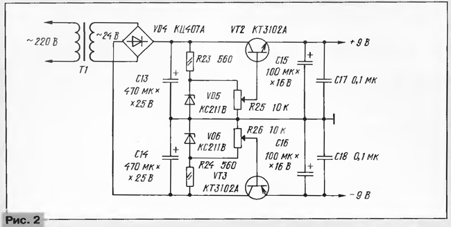
The power source (Fig. 2) produces bipolar voltages of ± 9 V. Reference voltages form thermostable Zener diodes VD5, VD6. Resistors R25, R26 set the required output voltage. Structurally, the power source is combined with the measuring part of the device on a common circuit board.

The device used variable resistors type SDR-22 (R21, R22, R25, R26). Fixed resistors R12 - R16 are of type C2-36 or C2-14 with a tolerance of ± 1%. Resistance R16 is obtained by connecting several matched resistors in series. Other types of resistors R12 - R16 can be used, but they must be selected with a digital ohmmeter (multimeter). The remaining fixed resistors are any with a power dissipation of 0.125 watts. Capacitor C10 - K53-1A, capacitors C11 - C16 - K50-16. Capacitors C1, C2 - K73-17 or other metal-film, C3, C4 - KM-5, KM-6 or other ceramic with TKE are not worse than M750, they must also be selected with an error of no more than 1%. The remaining capacitors - any.
Switches SA1, SA2 - П2Г-3 5П2Н. In the design, it is permissible to use a KPZAZ transistor (VT1) with letter indices A, B, B, F, I. The transistors of the VT2, VT3 voltage regulators can be replaced by other low-power silicon transistors of the corresponding structure. Instead of OU K1401UD4, K1401UD2A can be used, but then an error may occur at the limit of 1000 pF due to a shift in the input of the differentiator created by the input current DA2.2 to R16.
The power transformer T1 has an overall power of 1 watt. It is permissible to use a transformer with two secondary windings of 12 V, but then you need two rectifier bridges.
An oscilloscope is required to set up and debug the instrument. It is nice to have a frequency meter to check the frequency of the triangular oscillator. Exemplary capacitors will also be needed.

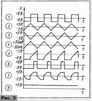
The device begins to adjust with the installation of voltages +9 V and -9 V using resistors R25, R26. After that, the operation of the generator of triangular oscillations is checked (oscillograms 1, 2, 3, 4 in Fig. 3). In the presence of a frequency meter, the generator frequency is measured at different positions of the switch SA1.It is acceptable if the frequencies differ from the values of 1 Hz, 10 Hz, 100 Hz, 1 kHz, but they must differ exactly 10 times between themselves, since the correctness of the instrument readings on different scales depends on this. If the generator frequency is not a multiple of ten, then the required accuracy (with an error of 1%) is achieved by selecting capacitors connected in parallel with capacitors C1 - C4. If the capacitances of capacitors C1 - C4 are selected with the required accuracy, you can do without measuring frequencies.
Next, check the operation of the OA DA1.3 (oscillograms 5, 6). After that, the measurement limit is set to "10 microfarads," the multiplier is set to the "x1" position, and a 10 microfarad capacitor is connected. At the output of the differentiator, there should be rectangular, but with tight, smoothed edges of oscillation with an amplitude of about 2 V (oscillogram 7). Resistor R21 expose the readings of the device - the deviation of the arrow at full scale. A digital voltmeter (at the limit of 2 V) is connected to the sockets XS3, XS4 and the resistor R22 is set to 1000 mV. If the capacitors C1 - C4 and the resistors R12 - R16 are precisely selected, then the instrument readings will be multiples on other scales, which can be checked with the help of model capacitors.
Measuring the capacitance of a capacitor soldered to a board with other elements is usually quite accurate in the range of 0.1 - 10,000 microfarads, unless the capacitor is shunted by a low-resistance resistive circuit.Since its equivalent resistance depends on the frequency Xc = 1 / ωС, in order to reduce the shunting effect of other elements of the device, it is necessary to increase the measurement frequency with decreasing capacitance of the measured capacitors. If, when measuring capacitors with a capacity of 10 000 μF, 1000 μF, 100 μF, 10 μF, the frequencies of 1 Hz, 10 Hz, 100 Hz, 1 kHz are used, then the shunting effect of the resistors will affect the instrument reading when the 300 Ω resistor is connected in parallel (an error of 4%) and less. When measuring capacitors with a capacity of 0.1 and 1 microfarads at a frequency of 1 kHz, an error of 4% will be due to the influence of a parallel-connected resistor having a resistance of 30 and 3 kΩ, respectively.
On the limits of 0.01 μF and 1000 pF, it is advisable to check the capacitors with disconnection of the shunt circuits, since the measuring current is small (2 μA, 200 nA). It is worth recalling, however, that the reliability of small capacitors is noticeably higher due to the design and the higher allowable voltage.
Sometimes, for example, when measuring some capacitors with an oxide dielectric (K50-6, etc.) with a capacity of 1 microfarad to 10 microfarads at a frequency of 1 kHz, an error occurs, apparently due to the capacitor's own inductance and loss in its dielectric ; instrument readings are smaller. Therefore, it may be advisable to make measurements at a lower frequency (for example, in our case at a frequency of 100 Hz), although the shunting properties of parallel resistors will already have an effect with their greater resistance.


