I'm trying to connect our rather old security alarm system to one of these
http://www.easydaq.co.uk/datasheets/Data Sheet 25 (USB8VI4DIOR card).pdf, so that I can monitor the zones remotely.
How old is your security system? Brand and model? Here in North America, alarm control panels aren't considered obsolete as often as Smartphones and laptops etc.
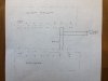
The alarm system has 8 sensor (zone) circuits coming in. They read 5VDC high, 2VDC low, when I measure across each circuit.
I infer that you're measuring across the zone loop (circuit) terminals with the loop wires attached and the sensors in "happy" state, i.e., doors and windows closed, no motion in front of motion sensors, etc. Try reading the terminals of a (for instance) door zone with the door both open and closed, and I think you'll find you get a different voltage with it open. Try reading the terminals with one wire disconnected, and I suspect you'll read around 12VDC to 13.5VDC, but I'm not sure, since I don't know the model of your alarm system's control panel.
I have wired in parallel to these circuits, and I thought I would be able to simply connect each sensor circuit directly to the opto-isolated digital inputs of the easydaq.
The sensing
devices (magnetic switches, motion sensor relays, etc) are either open or closed, depending on whether the door/window is open or closed, or something is triggering the motion sensor, etc
40-plus years ago, alarm sensor loops(circuits) were simply a loop of wire between the control panel and the sensors, so the loops were either open or closed, along with the sensors.
But for the last 30-plus years, all professional-grade alarm systems use End-of-Line Resistors (EOLRs) in series with the sensors, and installed at the sensor so that the entire loop is supervised. This makes it difficult for a potential intruder to circumvent the alarm system by shorting out the wires somewhere in the sensor loop. If the control panel doesn't "see" a certain resistance on the zone loop, then it sees the loop as "faulted".
Sometime later, I don't remember exactly when but no later than 20 years ago, all professional-grade panels started supporting double-balanced zone loops: Two resistors are installed on the sensor, one in parallel and one in series. Now the control panel never sees a dead open or dead short: It looks for specific current levels that correspond to a specific resistances; and even when the system is disarmed, a shorted (too low a resistance) or open (too high a resistance) condition may trigger a trouble or alarm response in the Panel, depending on how the zone is programmed.
But when I do, a 5v signal immediately drops to about 1.2v, making the alarm system fail and not driving the input of the easydaq board.
If by "fail", you mean that the alarm system starting making loud noises, or beeps or buzzing or whatever; then the alarm system didn't
"fail
": It responded exactly as it was designed to do. Putting an extra circuit in parallel on the zone loop lowered the resistance drastically, as evidenced by the voltage dropping to 1.2V The alarm system control panel saw a "fault" (alarm jargon) that shouldn't be there, regardless of Armed/Disarmed status.
Does anyone have a suggestion how I can work around this? Thank you so much.
I got about 3 long paragraphs into branching contingencies, before I realized that I don't know enough to give you suggestions. (1) I don't know the equipment you're working with (make and model of alarm system control panel) and (2) I don't really know what you're looking to do.
Do you really want only to "monitor the zones?" Meaning, be able to query the status of each zone, e.g, whether a door or window is open; or something is moving in front of a motion sensor? Or would you, like most people who want to monitor their alarm _system_ , i.e., whether it's armed or disarmed, be notified in an alarm or trouble event and which zone(s) initiated the event?
What you've described trying to do--taking an input directly off the zone loop inputs--can be made to tell you the zone status (faulted or unfaulted, aka, ready to arm or not ready to arm. But that is _all_ you can read from the zone loop inputs/terminals. The zones themselves are not armed or disarmed or bypassed or anything; and the zones don't go into alarm--they just fault and un fault and the control panel monitors the zones and follows its protocol about whether to ignore each of them, or generate an alarm, a notification, a trouble annunciation or whatever; depending on individual zone programming. If you want to know the status of your system (Armed? Disarmed? Alarm? ) that information is not available from the zone loop terminals.
In any case, unless your system is _really_ old (more than 25 years?) it's probably easier to interface remotely with the control panel and get all the information you can get at a keypad, _including_ status of zones. But I don't want to get into how unless I know what you actually want to do and what you're working with.