Maker Pro
Maker Pro

Blocking Oscillator

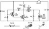
I used to have a circuit for a blocking oscilator that I used to change 12v to120 with a transformer,but I lost it. This is the closest circuit that I could find. I have tried different values of resister and capacitor to resonate with the transformer but I can't get it to go. Can someone suggest values that would work? I don't have a meter to measure the inductance of the primary of the transformer. It is an aproximently 2 amp transformer.
 

Attachments

  • led-torch-circuit-diagram-uses-blocking-oscillator-1367000374_500_295_75.jpg
    led-torch-circuit-diagram-uses-blocking-oscillator-1367000374_500_295_75.jpg
    11.2 KB · Views: 17
There is no resonating capacitor, that is not how a blocking oscillator works. You need a much smatller transformer which can be saturated with 1.5V supplied by the BC337.
1.5 V is low to turn on two silicon transistors in series.
A disposable camera will have flash circuit to do the job. Are they still available?
What is the maximum permisible voltage on the collector of the BC337?
 
I am transforming 12v to 120 v. I used a 3055 for the second transistor. It worked very well but I lost my old circuit diagram and that is the closest oscillator that I could find. The frequency should be around 60 Hz because it is a 60 cycle transformer, but it doesn't have to be exact. I will rectify it to dc. It is for a capacitive discharge ignition.
 
Your first circuit is similar to the circuit is a cheap solar garden light. The two transistors form a PUT (look it up) and create very low duration pulses that will not work well in a transformer.
 
li21044-jpg.44673


Used to make these CDI units for rc engines with just a basic hall effect as a trigger.
Later this went to microcontroller for advance but finally went to commercially available gear.
Mainly because winding the little step-up toroid transformer was a right PIA. Made a device which made this easier but still over a full day to make each unit.
Commercial units are a little pocket rocket motorcycle CDI ($7.00) and a CDI coil ($6.00) .
Only drawback is a couple of hours to make a pickup unit from a small relay as these operate from an inductive coil.All up less than $20.00.

Pic of original oscillator arrangement but it was limited by it's inability to deliver enough energy to charge the cap at high revs. Was fine for us with rc as we were only looking at a max of maybe 7-8000 rpm.
 

Attachments

  • Li21044.jpg
    Li21044.jpg
    138.2 KB · Views: 39
Last edited:
li21044-jpg.44673


Used to make these CDI units for rc engines with just a basic hall effect as a trigger.
Later this went to microcontroller for advance but finally went to commercially available gear.
Mainly because winding the little step-up toroid transformer was a right PIA. Made a device which made this easier but still over a full day to make each unit.
Commercial units are a little pocket rocket motorcycle CDI ($7.00) and a CDI coil ($6.00) .
Only drawback is a couple of hours to make a pickup unit from a small relay as these operate from an inductive coil.All up less than $20.00.

Pic of original oscillator arrangement but it was limited by it's inability to deliver enough energy to charge the cap at high revs. Was fine for us with rc as we were only looking at a max of maybe 7-8000 rpm.

Thanks for that circuit. Winding transformers is a lot of work. I see you used feedback from a second primary winding. That's a good idea.
Only 7000 to 8000 RPM!!! Ha ha
 
I measured the voltage on my Toyota pickup. It was 3000 volts. So 3000/12=250. 250X400=100000V!!!!! I think that spark would jump an inch gap! My voltage tester only goes to10,000 v.
 
Last edited by a moderator:
I tried to post a picture of my voltage tester but couldn't. What's wrong?
 
Last edited by a moderator:
Only 7000 to 8000 RPM!!! Ha ha

I don't see the humor in that.
Perhaps you would like to include some of your working examples.

I'd like to have 2 bob for every DIY that thinks building a CDI is easy peasy.
Big difference between seeing a spark jump whatever distance in free air to actually working inside a purpose built engine.
In fact there was a forum dedicated to building and they spanned over 3 different versions and went for years with many problems, the least of which were related to those wanting "30,000 rpm plus" ability.

The problem, as many have found with higher voltages, is they jump everywhere except where they are supposed to.
To me 8000 RPM is very high. But to you it is not. See the humor? And where did I indicate that building a CDI was easy? And I did build one before and it put out 10,000 volts but it used points to trigger, but I lost the circuit diagram. I will try to build your oscilator circuit tomorrow if it's too cold to work outside. Why can't I post a picture? I am thinking of a way now for analog advance and high RPM retard.
Oh, and that's what I was wondering about. How did you keep the spark from jumping everywhere?
 
And I did build one before and it put out 10,000 volts

Some of your comments show a distinct lack of knowledge on the subject.

The oscillator unit at best will give around 200v to charge the cap. Some were aiming at a 400v mark to run engines up to 30,000rpm but as far as I remember 15,000rpm was where most topped out.
The oscillator feeds the CDI coil ( completely separate item) which then gives the high voltage.

How did you keep the spark from jumping everywhere?

Most never did and hence the problem.
They wanted the higher charge voltage to facilitate the higher revs.
Sometimes it's noted the limitations are controlled by physical constraints.

Advance/retard by uC also attempted with varying results but took years of research and development and mostly failure in one form or another.
There was a basic unit that I used with a 12c508 which worked ok.
Only problem was a reprogram requirement for any new adv/ret curve.
 

Harald Kapp

Moderator
Moderator
I tried to post a picture of my voltage tester but couldn't. What's wrong?
Your picture may be too large. Try to resize it. I don't know what the size limit is, sorry.
Usually pictures can be uploaded by simply pasting them into the edit box. You may try another browser. I think Microsoft's IE can be a bit recalcitrant. Chrome usually works like a charm.
 
0210191602a-1.jpg this is the voltage tester that I used to test the CDI that I built a long time ago. The neon lites fire at 90 volts. I got like 20 for a dollar from poly packs years ago. Ha ha My CDI lit the last neon which is 10,000 volts. It may have even been15,000 volts, because the transformer put out 60 volts and 60X250=15,000. I need to build another tester with a higher voltage range. If someone wants to build one you can see the value of the resisters in the photo. I hope to get an oscillator running today! Note to self. Keep better notes of stuff that you build, so you don't have to go back and reinvent the wheel! Thanks to Herald Kapp. I cropped the picture and it loaded right up.
0210191602a-1.jpg
 
Top