Hello.
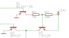
I need some help with this little BJT circuit. Its meant to switch the load at the Q3 collector on and off. Q1 &Q1 are controlled by 5V. Q1 should be able to limit the voltage at Q3 base, or in the other case, get it up to 24V, so that there is no voltage at Q3 base-emitter. Would this circuit work like this and do i just have to adjust the resistors, or am i completely off guard here? I'm kinda stuck here, so any help is appreciated.
Kind regards