Hello, I'm having some issues with small-signal analysis of BJT differential amplifiers.
Let's say I have this BJT differential pair and suppose that Q1 and Q2 perfectly match: http://i50.tinypic.com/14ahdgn.jpg
Suppose a small differential input is applied and consider the small–signal equivalent circuit:
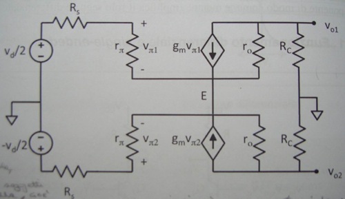
Having two opposite-phase inputs with the same amplitude makes the potential of the emitter E stuck at its initial value.
At this point, my book says that:
- If the potential of E is stuck at its value, then E can be considered as a ground point for the small-signal circuit;
- If E is grounded, then every point the two circuits have in common is grounded; this means that the two circuits become totally independent one from each other and I can solve the small-signal circuit of Q1 and Q2 separately;
Can anyone please explain me the reason for these two statements?
One last question: both small-signal circuits of Q1 and Q2 have an input impedance r_pi and an output impedance Rc || r_o .
What's the input/output impedance of the whole differential pair?
Thanks in advance for your time.
Let's say I have this BJT differential pair and suppose that Q1 and Q2 perfectly match: http://i50.tinypic.com/14ahdgn.jpg
Suppose a small differential input is applied and consider the small–signal equivalent circuit:
Having two opposite-phase inputs with the same amplitude makes the potential of the emitter E stuck at its initial value.
At this point, my book says that:
- If the potential of E is stuck at its value, then E can be considered as a ground point for the small-signal circuit;
- If E is grounded, then every point the two circuits have in common is grounded; this means that the two circuits become totally independent one from each other and I can solve the small-signal circuit of Q1 and Q2 separately;
Can anyone please explain me the reason for these two statements?
One last question: both small-signal circuits of Q1 and Q2 have an input impedance r_pi and an output impedance Rc || r_o .
What's the input/output impedance of the whole differential pair?
Thanks in advance for your time.
")