Maker Pro
Maker Pro

Beginner circuit problem

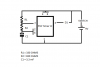
Hey all, this is my first post here. I've been having some trouble with a simple circuit I've been working on, thought I'd check with you guys for advice. Its a blinking light circuit, made from a 555 timer IC and various other parts. I tried to make a lil diagram (photo attached) to show exactly what I made (D1 = LED). Unfortunately, it isn't working.

By the equation 0.7(R1 + 2R2)(C1) = T
I should have: 0.7(1970)(0.0033) = T
T = 4.6s between each blink
However, since it isn't blinking AT ALL, I think the problem might be somewhere else rather than the ratios and whatnot.

Anything obviously wrong with my circuit? I'm in the dark here and I need some help.
 

Attachments

  • diagram.png
    diagram.png
    6.7 KB · Views: 124
Initially use a DC voltmeter , to read the voltage between the number 1 ground and pin 3 of the 555 to thereby see if you are getting a timely on off switching of that voltage .
If so , then use a proper value of dropping resistor in series with your LED.
The series wiring sequence is pin 3 to LED Then other LED lead to dropping resistor and other dropping resistor lead to pin 1 ground.
That's considering the proper polarity installation of the LED and that the LED has not already been damaged.

73's de Edd
 
Last edited by a moderator:
Ok I think the IC was fried, so I rewired it with new (same type) components. This time, the light would not turn on at all, until the IC became very hot, almost burning. Then the light turned on and stayed on without blinking. What am I doing wrong? I think I may be exceeding the 0.1 A maximum for the IC, although it never even blinks at all, even for a short duration of time. I feel like I'm mussing something up here so the capacitor is totally bypassed or something.
 
Have you got a series current limiting resistor in the diode circuit?

Sure you have the IC orientated in the right way?

Show us your actual circuit layout/wiring.
 
The LED needs a current-limiting resistor in series with it. Its typical current is 20mA and a red LED is about 2V so the resistor should be (9V - 2V - 0.2V)/20mA= 340 ohms, use 330 ohms. The 555 will be cooler if the LED and its resistor connects to the +9V, not ground.

What is 3.3mF? Capacitors do not have mF, they have uF. If it is 3.3uF then the light will blink at a frequency of 217Hz and look like it is turned on all the time. Your calculation shows 3300uF.

Why are your timing resistor values so low? Instead of 330 and 820 you can use 3300 and 8200 or 33k and 82k then the timing capacitor value can be 330uF or 33uF. You can even use 330k and 820k with a timing capacitor that is only 3.3uF.

The timing capacitor and LED must be connected with the correct polarity.
 
Its 3300 micro-Farads, I just don't have the symbol on my keyboard and I find it easier just to think of it as 3.3*10^-3 F or whatnot.

I replaced the LED with an incandescent bulb to prevent any problems with orientation. I also checked the voltage with a voltmeter, nothing was coming through at all. Looks like BlueJets was right about min resistances.
 
Getting the LED placed the right way is not a difficult task, nor working out the correct current limit resistor. Connecting an incandescent bulb in the output could well fry the chip. Maximum output is usually around 200mA. ( that's milli amp or 0.200 amp)
 
Sir Bnalex,

Ditto on the incandescent lamps current pull . . . .just put a 330 ohm in series with said LED and put it across the 9VDC and the way it lights up, is being the proper polarity, no risk involved with the LED.

I had considered you having come in with a tested schematic from a reference source But sometimes people switch between like values of the Time-Resistance-Capacitance in their computations an that throws the results off.
Like using Hertz-Ohms-Farads or Kilohertz-Kilohms-Microfarads or Megahertz- Megohms-Picofarads and then you throw in a value that is not BEING in that relationship. In your posted computation, it looks like that 0.0033 was setting you up to need to use Hertz and Ohms as the proper relationships.
Me I most commonly go for the Kilohertz-Kilohms-Microfarad relations unless I am figuring VERY LOW or VERY HI frequencies or time passages.

Refer to the mark up below and see if it doesn't get you going. It even considered a possible mis identification of the 555 basing from the top right illustration.
I chose an easily viewable 1 Hertz rate, then you modify if you are actually needing that 5 second time period.
If you look at the 330 ufd timing cap highlighted you can see its needed Ra Rb values and then look at the 1/10th decrease of using a 33 ufd and see the ratio metric shift of those resistors values.

HERE YA' GO . . . . .

upload_2017-12-31_17-10-6.png

73's de Edd
 
Top