Maker Pro
Maker Pro

Assistance in decoding a circuit diagram

I started following a YouTube tutorial to build an FM radio. After starting to connect, I realized that it's not as easy as I thought.


Until now I've connected a 10k preset with LM386 . But I'm not sure whether I've connected it in the right way and I don't want to proceed with such doubts.
I need a step by step guide for connection.
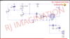
For example, to connect the 10k preset, connect the pin 4 of IC to left leg, pin 3 of IC to right leg. (Circuit not followed in my example) .
Check the attached file for circuit diagram

And I also would like to know why stuffs are connected in the way they are.
 

Attachments

  • Screenshot_20191028-060127.png
    Screenshot_20191028-060127.png
    111.9 KB · Views: 37

Harald Kapp

Moderator
Moderator
to connect the 10k preset, connect the pin 4 of IC to left leg, pin 3 of IC to right leg.
Pin 3 of the ic connects to the wiper which is commonly the center leg of VR1.
And I also would like to know why stuffs are connected in the way they are.
That means you'll haved to study electronics, learn the basics, learn to read and understand datasheets etc. There's no way this can be explained in a few simple statements.
We have a section on book reviews. You'll certainly find good recommendations there to get you started.
 
Hello, thanks for your time. Like you said, I'll connect the preset. But as I've asked, I need all other components' connection too. If you can, please have a look at the circuit diagram and guide me on connections.
 

Harald Kapp

Moderator
Moderator
I need all other components' connection too.
Zhe connections are all shown in the schematic diagram.
You may need to look up a datasheet of the two transistors to find which pins are base, emitter and collector respectively.
You'll also have to observe the polarity of capacitor C4. It is shown on the case of the capacitor.
All other 2-pin components can be connected eitehr way.
 

Harald Kapp

Moderator
Moderator
Sorry if I'm being too noob-ey
No need to excuse. WE all have been noobs one time or another.
Imho the important thing is that you accept your missing knowledge and are willing to learn.

You may want to consider starting with electronis kits instead of building things from scratch. Kits come with (more or less clear) instructions and all the right components. You'll have a quicker feeling of success which in turn may boost your motivation to go on.
 
Capacitor C4 has a + sign near one end. So the lengthy leg of the capacitor comes that side. But capacitor C3 does not have such signs. So can I assume that it is the positive side that gets connected to IC pin 5 ?
 
C3 is a 0.1uF (100nF) capacitor and is almost certainly non-polarised so can be connected either way round.
How do you define the positive side?
 
You are right. C3 is non-polarized. C4 is a electrolytic capacitor and so it's polarity is mentioned. So I am connecting C3 without any polarity in consideration
 

Harald Kapp

Moderator
Moderator
two of the three are likely short-circuited (measure resistance near 0 Ω with multimeter). Use one of these two and the remaining third for your circuit.
Polarization is irrelevant. However, depending on which one of the two connected pins the direction of tuning when turning the axle of the variable capacitor will change.
 
Most likely only two of them are connected, the other one is for stability when mounting on a board. It is also a non-polarized capacitor and can be connected either way around.

Bob
 
What meter have you?
A digital meter will have a resistance capability so you can determine whether two pins are connected together. It may also have a capacitance range to determine the active pins.
 

Harald Kapp

Moderator
Moderator
Which one do I follow now @BobK and @Harald Kapp
@BobK the 22 pF capacitor C1 is adjustable so I think I may be right.

I need some assistance in purchase. C3 and c2 of this circuit are 100nf capacitors. But I cannot determine which one to buy.
These are not critical. you can use any 100 nF capcitor as long as the rated voltage is 16 V or more. From your link e.g. this one, although it is rated at 63 V and therefore oversized.

You probably really should go for a kit.
 
Top