Congratulations, you seem to be doing *very* well.
Here are some pointers:
1) You should aim code that has *no* delay statements.
2) Separate the inputs (and maybe outputs) from the logic.
3) Make the code generic.
So how do you remove delay statements? Well, it looks like the debounce code in the code previous to last didn't have any, but your current code does.
The first thing to do is to treat the debouncing as a test which is carried out at a point in time, not over a period of time. The best way to do that is to restate the problem.
From here on in, you should retain all of this stuff as documentation of your work. You can probably put it in a block of comments in your code -- at least you won't lose it there. Doing this will mean that if you have problems you can get back into your head *exactly* what you were thinking and why.
A statement of the function we wish to perform:
We will no longer try to debounce the switch. We will, instead, only register a change of state if it has not changed for a certain time.
So, what do we know for each button? [and some names]
a) The current state (do we say it is currently on or off) [state]
b) The current input value (was it on or off last time we looked?) [lastVal]
c) The current input value (is it on or off now?) [val]
d) The last time we checked [lastTime]
e) The current time. [time]
f) The time the input state must remain unchanged to effect a change in state. [dbTime]
And what is the key value (or values) we want to set
g) The new state (do we say it is now on or off) [newState]
So now we can rewrite " We will only register a change of state if it has not changed for a certain time" first as an algorithm, then in pseudocode, then as a procedure.
If the [lastVal] is different to the [val] then set [lastTime] to [time] and [newState] to [state], otherwise if [time] exceeds [lastTime] by at least [dbTime] then set [newState] to [val].
We look at that, and we think about it, and it seems to say what we meant above, but we note that lastVal never changes. Clearly we've missed something.
At the end we need to add:
In all cases, set [lastVal] to [Val]
And now let's write that in something that looks like code, but without worrying too much about syntax (pseudocode)
Code:
if lastVal <> val then
    lastTime <- time
    newState <- state
else
    if (time - lastTime) >= dbTime then
        newState <- val
    endif
endif
lastVal <- val
This matches what we have said above.
But it's getting complex enough that we'll add some descriptive comments:
Code:
// We will only register a change of state if the input value has not
// changed for a certain time
if lastVal <> val then           // if the input value has changed
   lastTime <- time              // set the last time it changed to "now"
   newState <- state             // and return the old state
else                             // otherwise (input value has NOT changed)
   if (time - lastTime) >= dbTime then // has it remained stable long enough
     newState <- val             // change the state
  endif
endif
lastVal <- val                  // and retain the current input state
We look at it carefully, and we notice that there is a way through this where [newState] doesn't get a value.
After some thought, we realise that in all cases other than where [newState] receives the current value ([val]) it should remain unchanged. (and maybe we've also notes that we don't need to update [lastVal] unless [val] is different.
So we update the pseudocode to look like this:
Code:
// We will only register a change of state if the input value has not
// changed for a certain time
newState <- state               // by default the new state is the old state
if lastVal <> val then          // if the input value has changed
  lastTime <- time              // set the last time it changed to "now"
  lastVal <- val                // and retain the current input value
else                            // otherwise (input value has NOT changed)
  if (time - lastTime) >= dbTime then // has it remained stable long enough
    newState <- val             // change the state
  endif
endif
So now we can write some code:
But wait! First we need to separate the values our code will change from those it will not.
The ones it changes are on the left side of an assignment. these are
newState, lastVal, lastTime
And remaining unchanged are:
state, val, time, dbTime
newState is the main output of our function, so we can return this. The other variables will be passed to the function in a way that either allows them to be changed, or not...
This pretty much just involves getting the syntax right and adding extra stuff required by the language.
And how would we use that?
Something like this:
SwAState = debounce(SwAState, PinAVal, now, DBTIME, lastPinAVal, lastPinATime);
Now, that's all pretty cool, but it looks like quite a lot. Perhaps you notice that DBTIME is likely to be a global constant, and SwAState is both a parameter and gets the return value, and also that "now" is something we can possibly pick up internally to our function. Oh, and if PinAVal is just the digital value of a pin, why not get that internally too?
We could change our function, but that would make it more complex. So let's write another function which provides a simpler interface.
The requirements are:
A simpler debounce function which takes the digital pin number and sets the state variable using the debounce function.
And what we know:
a) Digital input pin [inPin]
b) state [state] (current AND returned)
c) internally access time [time]
d) internally fetch pin state [val]
e) internally access DBTIME global constant [DBTIME]
f) previous pin value [lastVal]
g) previous pin time [lastTime]
And the pseudocode is
time <- millis() // get the current time
val <- digitalRead(inPin) // get the current pin state
state <- debounce(state, val, time, DBTIME, lastVal, lastTime) // call the debounce routine
In this case, we are going to update the state passed to the function. So what should we return? Well, for various reasons, we should still return the state.
And then we can code it up...
And so how do we call that?
simpleDebounce(pinA, SwAState, lastPinAVal, lastPinATime);
Looks a little smaller, and if we want, we can also do:
if (simpleDebounce(pinA, SwAState, lastPinAVal, lastPinATime) == true) {
...
(We could do it with the previous version, but it uses a construction which looks odd to newcomers and might be misunderstood)
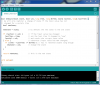
As promised, here is the code (unfortunately unformatted)
Code:
#define DBTIME 25;
bool debounce(bool state, bool val, long time, long dbTime, bool& lastVal, long& lastTime) {
// We will only register a change of state if the input value has not
// changed for a certain time
bool newState;
newState = state; // by default the new state is the old state
if (lastVal != val) { // if the input value has changed
lastTime = time; // set the last time it changed to "now"
lastVal = val; // and retain the current input value
} else { // otherwise (input value has NOT changed)
if ((time - lastTime) >= dbTime) { // has it remained stable long enough
newState = val; // change the state
}
}
return newState; // This is the new state
}
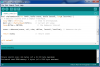
bool simpleDebounce(int inPin, bool& state, bool& lastVal, long& lastTime) {
// A debounce routine with a simpler interface.
long time = millis(); // time in milliseconds
bool val = digitalRead(inPin); // current pin value
long dbTime = DBTIME; // the debounce interval
state = debounce(state, val, time, dbTime, lastVal, lastTime); // debounce the pin
return state; // return state
}
And I think I'll end here...
") Not for me....bit like watching paint dry and wondering why the heck it won't dry.....lol
Not for me....bit like watching paint dry and wondering why the heck it won't dry.....lol