Maker Pro
Maker Pro

Amplify signal from piezoeletric

Then the output capacitor on the opamp circuit feeds the input resistance of the Arduino. What is its resistance? The Arduino input might already have a series capacitor that does not pass your extremely low frequencies.
 
On the datasheet of the ADC:
"The analog input resistance is claimed to be 100 Mohms.
During an actual sample, the input resistance is temporarily a lot lower as the sampling capacitor is charged up so it is recommended that whatever you connect to the A/D have an output impedance of 10k or less for best accuracy."
 
Why 10k and not 100M ohms?

52f3bddece395f19378b4567.png

And in the case of using an oscilloscope for testing?
 
Hi!
So, I have tried to implement the circuit! I don't believe I got 100% perfect results, but I got results, to which I owe you 100% :)!
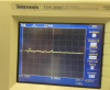
This is my general input signal (disconnected to amplification circuit):
upload_2017-7-5_19-13-42.png
With a gain of 3 or 6 (can't remember exactly) I got this:
upload_2017-7-5_19-14-43.png
When I see the input signal it also seems to attenuated.
Only setting the gain to 30 I got to see decent amplification (but with lots of noise)!
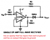
The circuit I used was the following:
upload_2017-7-5_19-27-33.png
(I started with C1 = 2.2uF but changing to 10uF got me better results.. with 2.2uF I couldn't barely see cough signal! only when i tapped the piezo with my finger!)
Any hints? :|
 

Attachments

  • upload_2017-7-5_19-14-23.png
    upload_2017-7-5_19-14-23.png
    991.2 KB · Views: 86
You do not show the value of R1. If it is 330 ohms then 48Hz is reduced by by -3dB and 4.8Hz is way down by -20dB.
A piezo is very sensitive to its high frequency resonances. It produces a strong low frequency signal when it is tapped with your finger. Tap it every time you cough.
 
You do not show the value of R1. If it is 330 ohms then 48Hz is reduced by by -3dB and 4.8Hz is way down by -20dB.
A piezo is very sensitive to its high frequency resonances. It produces a strong low frequency signal when it is tapped with your finger. Tap it every time you cough.
Sorry! R1 was always 100k!
 
The piezo "loading" with 100k (R between non-inverting input and 10uF) can't be causing the killing of the low frequencies?
 
A piezo transducer has such a horrible frequency response that I have never used one as a speaker or microphone.
Since your opamp has no part number then we do not know if it has a very high input impedance and low input current so the 100k bias resistor can be increased to 1M or higher. Then you could try it.
 
Which opamp part number and what is its supply voltage?
You did not attach a schematic of a full-wave rectifier circuit.
 
The bias current for the PO07 opamp is very low so you could try a 1M bias resistor to see if the low frequencies from the piezo are better. I have never tested that fullwave rectifier circuit.
 
Yes, try 1M as R1 in the preamp circuit.
Your preamp uses a single supply but your rectifier needs a dual polarity supply. Why don't you use a single opamp with a single supply for the fullwave rectifier? I use an MC33171 opamp that is a single opamp similar but better than an opamp in an LM324 or LM358. You could try a dual MC33172 opamp as the preamp plus rectifier if its noise in the preamp is not a problem.
 

Attachments

  • fullwave rectifier circuit.png
    fullwave rectifier circuit.png
    43.7 KB · Views: 70
Yes, try 1M as R1 in the preamp circuit.
Your preamp uses a single supply but your rectifier needs a dual polarity supply. Why don't you use a single opamp with a single supply for the fullwave rectifier? I use an MC33171 opamp that is a single opamp similar but better than an opamp in an LM324 or LM358. You could try a dual MC33172 opamp as the preamp plus rectifier if its noise in the preamp is not a problem.
Sorry, you mean only try the circuit you attached? With the R1 in that schematic R1=1M?
Will it work LM358 for testing only? (I have it on the lab)
 
The fullwave rectifier circuit I posted should be fed from a low resistance to ground signal source like from a preamp opamp powered from a dual polarity supply. If an LM358 opamp is used for the fullwave rectifier and its input is capacitor-coupled from the output if the preamp then the input bias current of the LM358 will cause its input to float high and it will fail to work properly.
 
Top