Maker Pro
Maker Pro

6 CELL LI-ION 22.2V BATTERY LEVEL MONITOR

I think I've missed the plot!
.
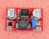
I have no access to a variable supply so had to make to do with what i had! I used a "buck booster" board which actually worked well with my earlier b.monitor! I could adjust it from 18v-30v.I used 2 batteries to get 8.00v

On 18v setting;
when the LED is green i got a reading of 15.84v
When " " " red " " " " 16.02v

R1=16.26V
16.34V

R4=16.81
16.61

No matter whether the supply is 18v or 22v, the battery monitor board is readsing 16v+ the b.booster seems impervious to any change & remains constant!
 

Attachments

  • Overlay-1.jpg
    Overlay-1.jpg
    50.9 KB · Views: 140
  • Stripboard-1.jpg
    Stripboard-1.jpg
    44.2 KB · Views: 176
You'd most probably detect some desperation on my part! I just wondered, what if I can modify & use the 2nd circuit on post #5 with hysteresis, if you think the problem with the current circuit may not be easy to solve? I'm sure you too must be frustrated by all this now? Could you possibly show me how to change the values for the circuit below so that I can use it instead?

Thanks.
 

Attachments

  • Battery Indicator Circuit-A.gif
    Battery Indicator Circuit-A.gif
    3.4 KB · Views: 196

KrisBlueNZ

Sadly passed away in 2015
You an use the red-green circuit in post #42 without any changes. You might want to increase the LED series resistor from 1k to 1.5k to reduce the LED current. Also you could increase the resistor that feeds the LM336Z to 27k as we calculated earlier.

I'm looking at your layout and description now. That three-colour circuit should work fine. There's probably just a wiring error.
 

KrisBlueNZ

Sadly passed away in 2015
Sorry for the slow reply. I think we should try to get the three-colour circuit working. Can you try this procedure?

1. Disconnect R6.
2. Supply about 18V into the circuit.
3. Set your multimeter for voltage and connect the negative lead to the 0V rail where it enters the circuit (track 12 on the stripboard).
4. Check the following IC pins for these expected voltages:
4a. pins 2 and 5 for +2.5V or close
4b. pin 8 for +18V
4c. pin 4 for 0V.
5. Measure pin 6 and adjust VR2 for about +2.5V. At a certain point the LED should change from green to red, or vice versa. If it doesn't, tell me (a) what colour is the LED, (b) what's the voltage on pin 7 of the IC, and (c) are you able to adjust the voltage on pin 6 to 2.5V with the trimpot?
6. Measure voltage with the positive lead to the positive rail (track 2 on the stripboard) and the negative lead to the top end of R5, i.e. the cathode of the LED. If the LED changes colour in step 5, measure the voltage for each colour. If not, just measure the voltage and tell me what colour it is.

Edit: I don't understand what you're saying in post #41 but you've done a great job with the board! Very nice work. Unfortunately I can't follow it well enough to spot any errors, but if you follow those steps we should be able to figure out where to look, at least.
 
Last edited:
First of all thank you for not giving up on me! Secondly I really admire your perseverance! Very encouraging indeed!

I've now checked the circuitboard numerous times,yet coudn't find anything wrong or any mistakes i may have made!

I've now completed all the tests & measurements as you had instructed.

The setup:

2x 4.1Li-ion batteries in series connected to a dc-dc buck booster.

DC-DC Buck Booster Description:

Module Properties:
non-isolated step-up module
Input voltage :3-30V
Output voltage: adjustable(4-30V)
Output Current: 2.5A(MAX)
Input Current: 3A(MAX)
Dimensions: L*W*H 4.3cm*3.0cm*1.2cm
Input : "IN+" is input postive, "IN-" is input negative
Output Voltage :4-30V continuously adjustable (building load debug)

The only anormally i noticed was that although I adjusted the voltage for 18v, but when i connected it to the circuitboard, the voltage dropped to 16v & decreased gradually until it settled down around 15+v & couldn't increase it no matter what!

The the readings i obtained are given below;

Supply voltage to the board =15.52v

Pin 2/5 =1.718v
Pin 8 =15.45v


Pin 6 when LED was green =1.696v
Pin 6 when " " RED =1.171

Pin 7 when Red LED on =0.678
" green =13-14v!

+V/ R5; LED =13.34V
" " [COLOR="[COLOR="Green"]LED[/COLOR] =2.059V

I hope all this makes some sense to you,if not please let me know & I'll try again. I'm rather puzzled about the supply v dropping by 3 v!
 

Attachments

  • Buck Booster.jpg
    Buck Booster.jpg
    23.4 KB · Views: 255

KrisBlueNZ

Sadly passed away in 2015
First of all thank you for not giving up on me! Secondly I really admire your perseverance! Very encouraging indeed!
Well, it's not just you that I don't want to give up on. I suggested a circuit, and I have reasonable confidence that it will work properly; I don't want to give up on THAT :)

The only anormally i noticed was that although I adjusted the voltage for 18v, but when i connected it to the circuitboard, the voltage dropped to 16v & decreased gradually until it settled down around 15+v & couldn't increase it no matter what!
That's a bit weird. Perhaps you should try using one of the batteries that you intend to use with the circuit when it's finished. You can adjust the trimpots to get the LED to change colour. You should find that the battery voltage doesn't vary much at all, apart from dropping slowly as the battery discharges.

Pin 2/5 =1.718v
OK, there's something wrong there already. That voltage should be 2.5V. Current through the 27K resistor into the LM336Z causes the LM336Z to regulate that voltage to the reference voltage, which is about 2.5V.

If the voltage is wrong, it could be that there's something else connected to that voltage rail - perhaps you've missed a track cut. Also check that the adjustment pin on the LM336Z is not connected to anything - you may want to cut the track on both sides of where that pin connects. Finally, double-check that you're using the right pins, the right way round.

Pin 6 when LED was green =1.696v
Pin 6 when " " RED =1.171
Pin 7 when Red LED on =0.678
" green =13-14v!
I'm not entirely sure what you mean here. But pin 7 SHOULD go high (13~14V) when the LED is green, so that sounds right.

+V/ R5; LED =13.34V
" " [COLOR="LED =2.059V
I think there's a mistake in the HTML coding of that last line in your post. But don't worry about that. The voltage between the positive rail and the LED common cathode should be around 3V when it's green, and around 2V when it's red. Is that right?
 
I will check LM336 again for soldering/connections errors.

I'm actually using the batteries which i intend using with this.

As for your last query... this is the values I got measureing between + supply & LED common cathode ie; R5. It works exactly the opposite way! I will recheck this report back

measured between +V & R5;

Quote:
+V/ R5; LED =13.34V...when LED is RED!
" " [COLOR="LED =2.059V when green

Cheers
 
Sorry for the delay, I've checked all the components & the board thoroughly yet coudn't find anything wrong! I also changed the LM336Z with an another but the voltage is still 1.7V! It could be this actually a 1.7v device?

Is the rail voltage supposed to be 15+v from the supply (batteries) when connected to the monitor circuit? 3v drop?

I think am well & truly stumped!?
 

KrisBlueNZ

Sadly passed away in 2015
Sorry for the delay, I've checked all the components & the board thoroughly yet coudn't find anything wrong! I also changed the LM336Z with an another but the voltage is still 1.7V! It could be this actually a 1.7v device?
No. You've connected to the wrong pin. The wire link that goes to pin 2 of the IC should connect to the middle terminal of the LM336Z, which is identified as "+" or "K" or "cathode". The other connection to the LM336Z is right.

Is the rail voltage supposed to be 15+v from the supply (batteries) when connected to the monitor circuit? 3v drop?
No. The circuit should draw less than 20 mA from the battery. Even 9V PP3-type batteries can supply 20 mA without dropping very much voltage.

Are you saying that with two new 9V batteries in series, the battery terminal voltage drops from over 18V to less than 15V when you connect the circuit?
 
Good grief & a very good catch! So that'sa what was the mistake! I should have known better. Good thing we were not discussing a post medical mishap after a surgery- I will of course connect it properly & report back. Thanks for spotting it!

Yes, it was when connected to the battery monitor board with the wrong connection!. I'm sure it would be ok once I reconnect the LM336 the correct way.
 

KrisBlueNZ

Sadly passed away in 2015
Actually no. Fixing the LM336Z connection probably won't affect anything much. You'll need to readjust the trimpots, but that's all.

I really need to know what the LED is doing, with R6 disconnected. Can you run through my steps in post #44 again? Especially steps 5 and 6.
 
The enevitable happened! The buck-booster decided to call it a day! So i am stuck without a proper voltage regulator. I'm trying to get an adjustable psu a.s.a.p & will run through the tests you've given in post #44 & report back.

Cheers
 

(*steve*)

¡sǝpodᴉʇuɐ ǝɥʇ ɹɐǝɥd
Moderator
The enevitable happened! The buck-booster decided to call it a day!

Do you mean this:

9722d1379588045-6-cell-li-ion-22-2v-battery-level-monitor-buck-booster.jpg


Because that's a boost, not a buck-boost module according to the specs you posted.

I've used some similar modules and found them to be quite reliable (I'm not sure I'd use them anywhere near their full rated current, and certainly not without more heatsinking). But you sound like you were using it at a very low current.

How (and why) did it expire. Was it an error on your part, or an actual failure?
 

KrisBlueNZ

Sadly passed away in 2015
You should be able to test using a couple of 9V PP3 batteries in series. You won't be able to get the threshold exactly right, but 18V is about right, isn't it?
 
Steve: Yes, That was exactly what I was using. Although i wasn't loading at with anything other than the battery monitor circuit, the supply voltage would drop from 18v to 16+v & wouldn't increase no matter what, but could regulate it at no load! I actually was using it with a 100 mA fuse preceeding it after the batteries.So i don't think it would have drawn more than 100mA! I may have inadvertently shorted something i guess.

KrisBlueNZ: Yes i did try with 2 x 9v batteries but these were way over 18v.(20v+) Ideally,I need a psu with a regulator I think & I'm working on it now.
 

KrisBlueNZ

Sadly passed away in 2015
Even if the voltage is wrong, you can still test the circuit. Once it's working properly and you get the three different colours, you can worry about setting the actual threshold voltages exactly.
 
Top