Maker Pro
Maker Pro

6 CELL LI-ION 22.2V BATTERY LEVEL MONITOR

Hi All,
I just discovered this forum to my great delight,hence thought I'd ask you experts out there
for help with this question.

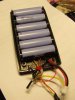
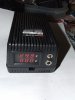
I have successfully constructed this circuit & running it with 4 x 186540 li-ion batteries at present. This circuit works very nicely,although I need to run this on 6 x li-ions instead. However, I'm unable to do this due to my inadequate knowledge of electronics theory!

I'd therfore be extremely grateful if anyone can show me or how to calculate the relevant component values & modify this for the following voltages;

Over 22.2V = Green On
Between 22.2V-18.00V = Orange (approximately)
Below 17.0V ? = Red


Thank you.
 

Attachments

  • batmon.gif
    batmon.gif
    9.8 KB · Views: 1,279
Last edited:

KrisBlueNZ

Sadly passed away in 2015
A simple solution would be to replace the two trimpots with multi-turn ones, and remove all of the resistors connected to them. That's R1, R2, R3, R4 and R7.

I would use something like this: http://www.digikey.com/product-detail/en/3296W-1-203LF/3296W-203LF-ND/1088051

This type of trimpot can be set very accurately. Avoid strong physical shock though, because they will drift slightly if banged hard.

That circuit should also be modified to use a temperature-compensated voltage reference instead of a 7805. A 7805 is a voltage regulator, rated at 1 amp, and is designed to power circuitry, not to provide an accurate reference voltage. I would use a TL431 - see http://www.digikey.com/product-detail/en/TL431ACLPG/TL431ACLPGOS-ND/660587

This will provide a 2.5V reference voltage. Download the data sheet (there's a link to it on the Digikey web page) to figure out how to connect it.

You will also need to increase R5 and R6 because of the higher supply voltage. The value you use will determine the LED current. Lower values will give brighter LED colours. Use around 1.5 kilohms for 10 mA LED current (fairly bright) or as low as 820 ohms for 20 mA LED current (brighter). You may want to adjust them separately to get the best orange colour.

If you need more details just ask.
 
Thank you ever so much KrisBlueNZ for your very detailed reply. Much appreciated. I never knew it would be that simple! Yes, I do have 3/4w multitrim pots. Do you think LP2954 (TI Instruments) precision LDO would be a better substitute instead of the TL431?
LP2954 has a ref voltage of 5v...or even LM1117T-5? Both have very low current draw!

So,do you mean that just removing R1,R2,R3,R4 & R7 would do the trick! Fantastic!

Yes, I will use higher value resistors for both LEDs just to give me adequate visual display & keep the current draw as little as possible.

I will redraw the circuit & post it for your approval.

Thanks again & best regards
 

KrisBlueNZ

Sadly passed away in 2015
I wouldn't use a voltage regulator when you want a reference voltage. Regulators are not intended to be as accurate, even ones that claim to be "precision". That's because components aren't very fussy about their supply voltages - most ICs can tolerate supply voltage errors of at least +/- 5%.

Yes, just removing those resistors will allow you to adjust the voltage thresholds over a wide range. But the adjustment becomes quite touchy, that's why you need multi-turn trimpots.

Eliminating those resistors also removes one source of error. All resistive devices are affected by temperature. But if your voltage divider is just two parts of a resistive track in a trimpot, both resistances will track each other (assuming all parts of the trimpot are at the same temperature), so errors cancel out. The only remaining error sources are the voltage reference (and the input offset voltage of the dual op-amp, which isn't much).

I meant to mention two other things.

1. This circuit doesn't have hysteresis, so changes between indications will not be clean and sharp. The circuit will probably oscillate on one of the transitions, because when the LED turns ON, the battery voltage will drop slightly (due to the LED current) and this will cause the LED to turn OFF, and the cycle will repeat. This isn't necessarily a problem; it just means that transitions between LED colours will not necessarily be clean.

2. The circuit will draw significant current. Mostly the LEDs, but also the op-amp, draw current. Therefore you shouldn't leave it connected across the battery unless it is being used in a continuous charge-discharge cycle.
 
Thanks again for your timely advice w.r.t the LM0875, I just left it in the circuit as it was,not realizing it was only a LDO! That's why it's always good get advice from experts like you. Good catch indeed! I've now chosen LM336Z-2,5 shunt regulator in preference to TL431. I gather from the data specs that LM336 has better noise figures than TL431. However,I'm not so certain if i have connected the adjustment pin correctly or not in the modified circuit. The LED voltage trimming instructions too seems a bit suspect,so please let me know. (it does work somewhat ok with 4S Li-ion batteries)

The LED should come on when;
Green- 22.2v & above
Yellow- between 22.2v- 18v
Red- Below 18v

As the absolute discarge limit for li-ion battery is 2.8v,I hope I've left a wide margin, ie:18v?

Btw, I just tumbled upon this circuit,which looks more promising if not a little more complex? Do you think this this is better a.f.s accuracy & current draw are concerned? Do you reckon that I could try this instead with the proper component values for 22.2v?

Yes, as you've correctly pointed out,the LED does shift color rather slowly,which could be critical in li-ion level monitoring!

Cheers
 

Attachments

  • Battery monoitor-A-1.gif
    Battery monoitor-A-1.gif
    38.2 KB · Views: 992
  • LED battery indicator.gif
    LED battery indicator.gif
    3.4 KB · Views: 3,406
Last edited:

KrisBlueNZ

Sadly passed away in 2015
OK, the LM336Z-2.5 is a good choice.

Your first diagram is right except that you need a resistor from the positive supply to the cathode of the LM336Z-2.5 to supply current to the LM336Z-2.5 so it can operate. This is the 5.6k resistor in the second diagram. It needs to supply at least 0.4 mA, which is the minimum current the LM336Z-2.5 needs for regulation, according to its data sheet.

The value is calculated using Ohm's Law, R = V / I, where R is the resistance, in ohms; V is the voltage across the resistor, in volts, which is the minimum supply voltage minus the 2.5V that's dropped across the LM336Z-2.5, and I is the required current, in amps, which is 0.0004, but I will include a safety fudge factor and make it 0.0006.

Assuming the minimum supply voltage is, say, 15V, the minimum voltage remaining across the resistor will be 12.5V. So V = 12.5 and I = 0.0006, so R = 12.5 / 0.0006 which is 20.8 kilohms.

A close preferred value is 18 kilohms. This will ensure the LM336Z-2.5 receives at least 0.694 mA of operating current as long as the battery voltage is 15V or more.

The second design has hysteresis (because of the 4.7M feedback resistor) and will switch cleanly, but it only has one voltage threshold. The second op-amp is used as an inverter, to drive the other side of the bi-colour LED to the opposite state. So the LED only indicates red or green, never orange.

The second design also uses a resistor in series with the adjustment trimpot, which will affect its temperature stability slightly. This is probably not an issue in practice, because the switching voltage thresholds don't have to be too precise.

Returning to your first circuit, I think the orange-to-red transition is the one that will be gradual; the green-to-orange transition should be clean. You can add positive feedback (hysteresis) by connecting a high-value resistor between pins 7 and 5 of your LM358 but you also need to connect a resistor between the wiper of trimpot V2 and pin 5. The ratio between the two resistances determines how much hysteresis you will get.

To find out how much hysteresis you need, get your oldest battery in a state of low charge and measure how much the terminal voltage drops when you connect an LED with a series resistor across it. Use the same series resistor that you intend to use with the green element in your circuit, i.e. R6. Let me know how much the battery voltage drops when you connect the LED and I'll show you the calculations.
 
Last edited:
Your explanation is just perfect! Excellent! (no flattery intended) Thank you again!
I am now actually begining to understand how this circuit works! I've redrawn & changed R1 to 18k which you've kindly worked out for me.So then R3 & R2 in the positive feedback loop of IC2 which determine the gain or hysteresis right; to state the obvious!

I don't have any rundown/low voltage Li-ion batteries a.t.m. A variable psu would have been the ideal, yet don't have one. I could perhaps use a few alkalines or NiCds in series (to make up to 2.9-3v) which I seem to have in every cupboard & drawer in the house! I'll find a way somehow.

I've already ordered a few LM336Z & 10k trimpots as I have only 5k's on hand.Perhaps 5k will suffice? I'm actually in the midst of moving house temporarily,so this should give you some respite from my constant nagging until the parts arrive.

In the meantime please take a look at the revised drawing & see if i've made any mistakes or not.

Cheers
 

Attachments

  • Battery monoitor-A-1.gif
    Battery monoitor-A-1.gif
    38.4 KB · Views: 428

KrisBlueNZ

Sadly passed away in 2015
You catch on quick :) That circuit looks good.

The reason I suggested testing with a run-down battery is that you need to set your hysteresis so that it's greater than the change in terminal voltage when the green LED element changes state.

When the LED changes from ON to OFF or from OFF to ON, the current drawn by this circuit changes, and this will cause the battery's terminal voltage to change, because of the internal resistance of the battery. You need to make sure that the hysteresis in the circuit exceeds that change, so you will get a clean switching action.

Another approach would be to reduce the change in load current. This can be done by controlling the LED in a different way. Instead of switching the top end of the current limiting resistor, you can connect the top end of the current limiting resistor permanently to the supply voltage, and connect a transistor or MOSFET ACROSS the LED. When the transistor is turned ON, it shorts out the LED and removes voltage from it, so the LED turns OFF; when the transistor is turned OFF, it allows voltage across the LED, so the LED turns ON.

You could use a 2N7000 or BS170 MOSFET, with its source to the 0V rail, its drain to the anode of the green LED element, and its gate driven from the op-amp output via a 100k+100k voltage divider (20V on a MOSFET gate is a bit too much). The op-amp needs to have its inputs exchanged, because its output is now low to enable the LED, instead of high to enable it.

If you make that change, you may not need positive feedback on that op-amp. But if you still do, since the inputs are exchanged, the trimpot will now feed directly to the op-amp's inverting ("-") input and the left hand hysteresis setting resistor will now connect to the reference voltage.

The trimpot value is not important apart from the fact that a low resistance will waste current unnecessarily. I = V / R; if V = 20V, a 20k trimpot will waste 1 mA but a 5k trimpot will waste 4 mA.
 
Phew! I got it right! I think I'll tread a little cautiously at this juncture & follow through the1st method you have shown me. The more I look at it the better i understand it! Simple,yet very neat & tidy. You have actually triggered the art of analyzing a circuit from a design perspective in me! I realize now how all the small nuggets of information you've given here are so invaluable in a circuit design & gives me some idea as to how designers like you may think with regard to circuit design! I wish I had shown more interest in design than just copying & building circuits much earlier.....never the less there's still hope, I hope! Lol!

I'll get back to you once I get the LM336 & have actually built it. In the meantime, my sincere gratitude to you for your excellent guidance & above all your immense patience!

Thanks a million!
 
While waiting for the parts for my battery level monitor to arrive I just put together this battery case for my 6 pack Li-ion battery psu. I salvaged the casing from an old psu which had just enough space for the 6 batteries & everything else!

The batteries are wired to a 6S PCM pcb directly,which has cell balancing,min,dicharge cut off, & short circuit protection. Ideally I would have liked to wire it through a SPDT switch,but it draws only 4uA acc.to the specs....I'll see how much current it actually draws before I decide.

I also incorporated this LED voltage/current monitor to keep an eye on while charging... Unfortunately it has a fairly high current draw of 20mA,so I connected to a switch so that I can switch it on only when I need to. The DC socket is common for both charging & discharging.
 

Attachments

  • Battery Case-1.jpg
    Battery Case-1.jpg
    49.6 KB · Views: 291
  • Battery Case with PCM Wiring.jpg
    Battery Case with PCM Wiring.jpg
    59.9 KB · Views: 310
  • Battery Casing with Batteries.jpg
    Battery Casing with Batteries.jpg
    52.1 KB · Views: 332
  • Battery PSU-1.jpg
    Battery PSU-1.jpg
    47.1 KB · Views: 317
Last edited:
Hi KrisBlueNZ,
The LM336Z arrived at last from the far east,so I managed to solder everything on to a copper strip board.

W.r.t to the circuit, since Li-ion batteries have an absolute minimum discharge voltage of 2.8v, I've chosen 18v as the safest min for my 6 pack! Then following your calculations for 18v, the R value was 25.8k to 27k (16.2v) the nearest value, as 22k would only give 13.2v! I hope I've done the math correctly!?

I also checked the voltage drop across the green LED through a 1k5 R on a rundown 9v alk.battery.

Open battery voltage = 9.43v
Through 1k5 resistor = 9.25v
Voltage drop = 0.18v

Taking your very noteworthy hint, I've increased the value of both RV1 &RV2 to 10k! I've also increased LED load resistors R5 & R6 to 1k5 from 1k to keep the circuit current draw as minimal as possible.

It would be just great if you'd possibly show me as to how much gain or hysteresis I should have & how to calculate the values of R2 & R3. Thanks to you in no small measure, I've learnt a lot with this circuit!

Cheers!
 

Attachments

  • Battery monoitor-A-1.gif
    Battery monoitor-A-1.gif
    32.5 KB · Views: 324
Last edited:

KrisBlueNZ

Sadly passed away in 2015
You've calculated a good value for R1 but I don't think you understand the calculations, so I'll explain them in detail.

R1 determines the current that flows through the LM336Z. The LM336Z needs at least 0.4 mA in order to regulate properly. The current can be higher than 0.4 mA, but it must not be lower. For safety I would round the minimum value up to 0.5 mA.

Current through a resistor can be calculated using Ohm's Law, which says

I = V / R
where I is current, measured in amps; V is the voltage across the resistor, in volts, and R is resistance in ohms.

Since we want to guarantee a certain minimum current, we have to look for the cases where current will be lowest and design for that. Looking at Ohm's Law shows that lowest current will occur at lowest voltage, and highest resistance.

So we have a minimum supply voltage of 16.8V (from 2.8V * 6). With 2.5V across the LM336Z, there will be 14.3V remaining across the resistor. And we need at least 0.5 mA flowing in the LM336Z. Rearranging Ohm's Law gives:

R = V / I
= 14.3 / 0.0005
= 28.6 kilohms.

This is the maximum resistance. Increasing the resistance above 28.6k will reduce the current. So we need to choose a preferred value that is less than or equal to 28.6k. So 27k is an appropriate value.

So you got the right value for R1: 27k.

Re the hysteresis calculations, you've measured the right way, but you need to measure the voltage change under load on the type of battery that you'll be using with this circuit. Measuring a 9V Alkaline battery won't give the same result because different battery types have different characteristics.

Warning: the calculations for R2 and R3 are going to be messy!
 
Thank you, thank you...sooo much for responding so quickly! I think I understood the "calculations, it's just we have defferred on the minimum voltage values perhaps?
I actually chose 18v while you had selected 16.8v as the absolute minimum.Since these batteries would never recover once they go below 2.8v, I've left this safty margin at 18v! I hope I've made my case?(lol)8

Here's how I calculated:

18v-2,5v = 15.5v (v. drop across LM336Z)
Current through LM336Z ........ 6mA (0.0006)

V/I=R
15.5/0.0006
25,8883 = nearest value 27k.....this is how i arrived at this value!

Please do correct me if I had done it wrong again!

Ok, I didn't realize this fact...I'll do the measurement with a li-ion...the only problem is that all these are fully charged!

W.r.t to the messy calculations,no problem on my part. I am all willing & ready to learn!

Regards
 

KrisBlueNZ

Sadly passed away in 2015
OK, your calculations are fine except that you need to choose a preferred value that's LOWER than the calculated value, because that will give you a higher current. All the approximations need to be in the direction of increasing the current, because you are trying to meet a minimum current specification.

The next preferred value below 25.8883 kilohms would be 24k or 22k but I think 27k is fine because the safety margin between 0.4 mA (the data sheet figure) and 0.6 mA (the figure I chose) is unnecessarily wide.

If you calculate the minimum current using the actual final resistor value, assuming a 1% resistor, you get R = 27,000 * 1.01 = 27270 ohms, then
I = V / R
= 15.5V / 27,270 ohms
= 0.568 mA.

That's less than the 0.6 mA that I initially suggested, but it's still very comfortably greater than the 0.4 mA specified on the data sheet. So 27k seems reasonable.
 
Thanks again.I do understand it now. So 27k should be ok then? B.t.w, On second thoughts, if this means taking up a lot of your valuable time, can I then just do it without the "hysteresis" in the circuit?
 
Last edited:

KrisBlueNZ

Sadly passed away in 2015
My time isn't THAT valuable LOL :)

But yes, you can change the circuit as I described in post #8 so that when the green LED turns ON, the load current on the battery doesn't increase. In fact, it decreases slightly. This is because the LED's drive current, through the 1.5k resistor, is always present, but when the LED is OFF, that current is shunted away from the LED by a MOSFET (or you could use a normal bipolar transistor).

This method wastes current, because the green LED's 10~15 mA current is always flowing and loading the battery. So perhaps it's not such a good idea if the circuit will be permanently connected to the battery.

What do you think? I'll have a think about other options as well.
 
Was I clean bowled or was it a LBW? (lol) I will of course accept your very kind offer to guide me through the calculations! As you'd correctly pointed out it should consume as little current as possible otherwise the whole purpose of using this circuit is lost!

Yes, do please explain how this is done. I'm all wired up & nowhere to go!(lol)
 

Attachments

  • B.Monitor-640-2.jpg
    B.Monitor-640-2.jpg
    27.6 KB · Views: 283

KrisBlueNZ

Sadly passed away in 2015
I'm still thinking about a good way to deal with the current consumption issue.

The best way would be a switching converter that would boost the current while it reduces the voltage, so the LEDs could run at 10~15 mA but the load on the battery would be less than that. But that would add significant complexity to the design.

At the moment the design I'm thinking about will draw a fairly constant 10~15 mA from the battery. That's no worse than your original design, which always has at least one LED illuminated. It will need a couple of transistors and resistors in addition to your original design. Does that sound OK?

I think avoiding significant changes in current drain is a good way to avoid the problem of indefined indications due to the internal resistance of the battery causing the terminal voltage to change as the indication changes and causing a feedback situation.

I'll get back to you with a modified design, ok?
 
Top