Maker Pro
Maker Pro

555 timer to turn on 2nd 555 timer

Hi Alec,
Today I worked on breadboarding your first CD40106 schematic. Unfortunately, in doing so I just couldn't get it to work right (I tried re-wiring, replacing components (in case maybe they were bad. I went over everything and even put sliver's of pins in to hold possible loose pins. Couldn't figure out what I was doing wrong.
I was about to send you a reply relative to that, however when I got on to do a reply just now, I saw your latest post with your improved circuit diagram. That's fantastic !
Kinda tired now, tomorrow will do the improved circuit. Thank you so much for this latest schematic and the info in your post. Looking forward to doing it.
Richard
 
Good luck with the build. Take particular note of diode orientation and the way the 40106 is wired in the latest version. Since now only three gates (d,e,f) are paralleled it is not advisable to drive a LED from their output. LED current causes a voltage drop across the internal resistance of the IC, which reduces the servo drive capability. Besides, since the oscillator runs from the get go, a LED there won't indicate much of use.
I should have mentioned at the outset, in case you weren't aware of it, that CMOS circuits are static-sensitive and due precautions should be taken when handling them.
 
Hi Alec,
Spent most of today breadboarding the latest schematic. I understood the schematic and all you wrote in your posts (which are really nice to know while breadboarding the schematic). Sorry to say I was unable to get it to work right. The servo wouldn't turn CW after delay, nor CCW on subsequent power up. See attached for my notes / observations.
Any thoughts ?
Richard
 

Attachments

  • Notes Observations.pdf
    109.2 KB · Views: 74
The detailed notes are very helpful.
The BC547 will be fine.
Can you post the pin numbers you used for the inputs/outputs of the gates that I identified as U1a to U1f in the latest schematic?
If pin 1 is the input to U1a then something seems miswired if its voltage doesn't rise above 1.8V. Either that, or the resistance of you test meter is preventing C1 charging.
Going to 260nF for C3 may (but unlikely) have resulted in pulses slightly too wide to be interpreted correctly by the servo.
Which of the two LEDs is 'the red liight' in your note, and is it wired as per the latest circuit?
As a diagnostic test, temporarily disconnect D3 and the servo. Does LED1 go on immediately at power-up? Does LED2 come on only after the delay? (Don't expect either LED to be bright, unless they are specifically high-brightness types).
 
HI Alec,
Thank you.....yet again !
Below is schematic with my pin #'s etc.
Attached are photos of breadboard fyi. Also, please disregard all the copper vertical pins, they are just "place holders" to assure none are loose. None of the copper place holders are touching anything other than the pins they are in. I made sure none of the component pins were touching anything other than the socket they were going to.
To answer your other questions.
1. After removing the 3 servo wires & removing D3, when I power ON, the Green light comes on immediately and the Red light immediately blinks then goes OFF and stays OFF. (since I wasn't sure if you just wanted me to lift it out of the circuit OR lift it out and put a jumper in it's place....so I did it both ways...with same results.
2. The circuit acted the same with or without the test meter being used.

I hope I answered all your questions. After you read this post, let me know if you still think that I miswired something....('m having a hard time locating that)
Are there other little diagnostic things I can do to figure out why I'm not getting full power to pin 12 to maybe find the miswiring?, Richard
pin numbers on schematic.GIF
 

Attachments

  • IMG_3111.JPG
    IMG_3111.JPG
    144 KB · Views: 73
  • IMG_3112.JPG
    IMG_3112.JPG
    123 KB · Views: 60
  • IMG_3113.JPG
    IMG_3113.JPG
    119.3 KB · Views: 58
  • IMG_3114.JPG
    IMG_3114.JPG
    121.6 KB · Views: 51
  • IMG_3115.JPG
    IMG_3115.JPG
    120.4 KB · Views: 62
  • IMG_3116.JPG
    IMG_3116.JPG
    78.4 KB · Views: 58
  • IMG_3117.JPG
    IMG_3117.JPG
    100.1 KB · Views: 61
  • IMG_3118.JPG
    IMG_3118.JPG
    110.4 KB · Views: 59
  • IMG_3119.JPG
    IMG_3119.JPG
    87 KB · Views: 52
  • IMG_3120.JPG
    IMG_3120.JPG
    104 KB · Views: 50
  • IMG_3121.JPG
    IMG_3121.JPG
    111.9 KB · Views: 55
  • IMG_3122.JPG
    IMG_3122.JPG
    111.3 KB · Views: 56
That info should help the diagnosis.
How long did you wait for the red LED to come on? I see you now have 100k in place of the SetDelay pot. That will increase the delay to about 11 sec.
 
You have pin 2 going to LED1 (correct), but also to 2 other things (wrong).
Pins 3 and 4 seem to be shorted together?
Pins 4 and 5 don't seem to be connected to D2 and R5?
 
Last edited:
Alec,
Thanks for catching my oops. I decided to re-wire the board so it can be diagnosed in just a few minutes.....I laid everything out much neater and less cluttered...I was getting a bit confused.
So Below is the latest...and attached are detail photos. At the moment....when I power up, LED2 immediately goes bright for an instant then down to dim level. No servo movement. I changed C1 to 47uf. I have to believe that I am mis- wiring something still. Suggestions ?
And thank you so much for sticking with me on this.....I am determined to get your circuit working.
(I apologize for any inconvenience I may have caused...)
Richard
very latest.GIF
IMG_3124.JPG IMG_3126.JPG IMG_3127.JPG IMG_3128.JPG IMG_3129.JPG IMG_3130.JPG IMG_3131.JPG IMG_3132.JPG IMG_3133.JPG
 
Alec, good news / bad news. The good news....first I added two wires from prev post....C2 to pin 7 and pin 7 to ground....I had those before but missed putting them back....see attached....then I was trying out the circuit the red light went to full brightness when I accidentally touched C2. Bottom line, I replaced C2 with lesser capacity (closer to 220nf) and no loose capacitors. The red light now stays at full brightness from the moment I turn it on.
The bad news is I still have no servo movement. I must be misinterpreting something in the schematic.....it has to be a miswired connection.....but where ? Going to bed now, it's after midnight. Richard
 

Attachments

  • IMG_3135.JPG
    IMG_3135.JPG
    103.8 KB · Views: 59
  • IMG_3136.JPG
    IMG_3136.JPG
    116.1 KB · Views: 61
You have pin 3 going to C3 but not to R5, R8 and the 'width pot'.
Pin 5 should not go to pin 8.
Pin 6 should not go to pin 7 but should go to pin 8.
Pin 7 should go to ground instead of to pin 9.
Pin 11 should go to pin 13.
Pin 14 should go to the +ve rail.
C2 should connect between the +ve rail and the -ve rail (as closely to the IC pins 7 and 11 as possible).
 
GREAT NEWS ! ALL DONE !
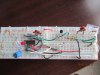
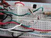
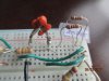
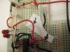
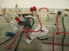
I re-did the breadboard using the "correct" pinout labels and your prev post comments.
It didn't work quite right... after delay it would move servo, but I couldn't get it to reset....probably a minor mis-wiring on my part.

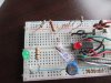
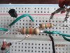
However, while trouble shooting I came across a trial & error solution.
I made ONE change...I added a Normally Open (NO) Momentary switch between Pin 3 and R5.

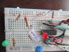
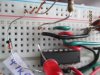
Works as follows: Starting with servo in fully CW position, turn power ON, after delay servo moves CCW. Then I "press" the NO switch (closing pin 3 to R5) and servo goes CW...I then turn power OFF. And it's now ready for the next use.

The only difference between the intended schematic and adding my NO switch, is that for the intended schematic, a reset would happen by turning power OFF before delay, to reset the servo. and with mine I press the NO switch to reset the servo.

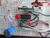
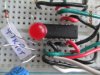
Bottom line.....when servo moves CCW that will deploy the parachute. Upon retrieval of the rocket, I would reset the circuit by pressing NO switch, then turn power OFF.
Does this seem OK to you ?

I really want to thank you for all you've done. As you observed, I'm "new" to circuit boards, inverter trigger, transistors, capacitors, diodes, and reading schematics.

You've helped this 73yr old Senior Citizen more than you can imagine...I learned so much in the past 10 days or so.
Richard
 
As you found, consulting the relevant datasheets is essential before/when working with components you're unfamiliar with :).
Does this seem OK to you ?
Hey, if it works for you, it works! The non-reset bug could be due to a poor contact in the breadboard. Poor contact is a common problem with breadboards. Building the circuit on a pcb is the cure.
 
Now that I have a working circuit, so I understand it better, what is the purpose of C2 and C3 ?
(I believe C1 and 10K pot are the RC components to set the delay with equation t=1.1xRxC ).
thanks !
 
C1 and the 100k pot set the delay time.
C2 is a 'decoupling' cap which holds a reservoir of charge to help out the battery when there is a sudden current demand. It is good practice to have such a decoupling cap with most ICs.
C3 is the oscillator timing cap.
C3 + R5 set the servo pulse repetition period (~20mS).
C3 + R6 + R5 + the 10k pot set the pulse width at ~2mS.
When Q1 switches on at the end of the delay, R8 gets connected effectively in parallel with R6 and the 10k pot, reducing the pulse width to ~1mS.
 
Hi, in converting the breadboard to a printed circuit board, the pcb works exactly as the schematic intended. However I do have a minor problem.....the servo only rotates about half of it's normal travel. How can I increase the travel ?
FYI....using a jumper I get the servo to rotate the full travel (by touching pin 12 to either pin 13 (or pin 11), so I know there is enough battery power and that the servo functions ok when using the jumper to cycle it. Any suggestions ?
Thanks, Richard
 
Hi, Thanks for the suggestion. I replaced both R6 & R8....I think I got a bit more travel.
(FYI....full travel is 0 to 220 degrees....currently I go from 130 to 220 just 90 degrees ). Toggling the on/off immediately after I turn it on resets it to 130, then I shut it off before the delay time. When I turn it back ON it after the delay the servo moves to 220 degrees (about 90 degrees of travel). And 90 degrees will work for my application. So the circuit is doing exactly what it was supposed to do..but would like the more travel if possible. During the reset it only goes to 130 not back to 0.
 
Top